Explore the world of Concorde with Heritage Concorde
Concorde top Forward engineers panel
This section of the engineers panel covers the following;
1. Cold air outlet for flight engineers use
2. Ground Hydraulics
3. Clock and Brake controls
4. Brake Temperature
5. Intake Pressure ratio
6. Cabin pressure control
7. Engine control and warning, Secondary air door selection


Click below to find out more
Engineers panel air outlet

Cold air outlet for the engineers station, the air is cooled using the airconditioning the system is duplicated throughout the cockpit and main cabins.
Ground Hydraulic controls

Ground generation is provided by two electric pumps that can be selected to pressurize the main and standby systems while the aircraft is on the ground. The maximum delivery pressure and flow of the electrical pumps is less than that of the engine driven pumps.


Clock, Lighting control, Brake temperature controls & pressure

Flight Engineers panel Lights
Flight Data Recorder MI


Flight Engineers panel clock
The Clock on the engineer panel does not include elapsed time as illustrated below.

Brakes Pressure, Fans and overload indication


Brake temperature gauge and warning


Intake pressure ratio error gauges


Cabin Pressure Control & Monitor

Cabin pressure in controlled and maintained by using discharge valves and a ground pressure relief valve to control the outflow of conditioned air from the pressurised zones.
Cabin pressure control includes two identical systems SYS 1 and SYS 2. There are two discharge valves, one forward and one aft for each system. Both systems are automatic and operate to the requirements selected on the cabin altitude selector, throttle settings and weight switches. Limited manual control of the pressurisation is
provided on each system. This permits the direct selection of either of the discharge valves to shut.
The cabin differential pressure is limited to 10.7 psi by the amplifier of the selected system and to 11.2 psi by the cabin pressure limiter of each discharge valve.
The cabin altitude is limited to 11,000 ft by a cabin altitude limiter on each discharge valve and to 15,000 ft by the discharge valve geometry when all four air conditioning groups are operating.
Provision is made for rapid dumping of cabin pressure within the range of the cabin altitude limiters.
A thrust recuperator is fitted to SYS 1 forward discharge valve; it is controlled by differential pressure.


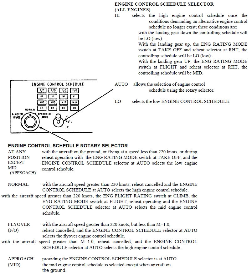
Engine control and warning captions

This small panel includes warning captions, engine control schedule, secondary air door control, fuel heaters, engine 4 N1 limit, engine recirculation valves


Takeoff CG Switch (Encapsulated)


