Explore the world of Concorde with Heritage Concorde
Concorde Variable (Hinged Buckets) Exhaust Nozzles
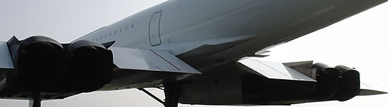
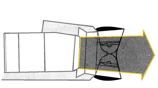
The rear of the powerplant comprises the final part of the powerplant exhaust assembly, the design responsibility for which was place with the French company Snecma. This part of the exhaust assembly comprises of a variable exhaust, which consists of a primary nozzle and a secondary nozzle, the secondary being an arrangement of hinged ‘buckets’ or ‘clamshells’ whose position can be varied to control the exhaust in the most efficient way during all stages of flight.
The prototypes and the first pre-production aircraft (Concorde G-AXDN, seen in the picture below) were equipped with a conventional-type nozzle as used on a number of military aircraft. But after a great deal of research work was carried out mainly aimed at reducing noise. A major change to the nozzle design was made and fitted to the second pre-production aircraft, 02, and from that time onwards the TRAType 28 nozzle was introduced and fitted to all production Concordes. This introduction saved weight, and reduced noise when the reverser buckets were partially closed.


Concorde G-AXDN the British pre-production airframe at Duxford UK, showing the Conventional-type nozzle that was also fitted to the two prototype Concordes
Concorde F-WTSA the second pre-production airframe showing the major change to the nozzles. She was the first Concorde to have the 'bucket-type' secondary engine nozzles
Concorde G-BOAC showing the new TRA nozzle that was fitted to all the Production Concordes
There are two elements that form the variable exhaust system for the powerplant of Concorde. These are separate yet integrated to a common purpose. The two elements are firstly the Primary Nozzle and then the Secondary Nozzle. The primary nozzle sits at the end of the jet-pipe, and is a ring of petals, each one being operated by its own extending air-jacks. These operate in unison to vary the diameter, and therefore then the area of the jet pipe exit.
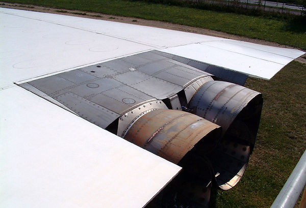
The secondary nozzle assembly surrounds the primary nozzle, it has eyelid-like doors which are called ‘buckets’. These buckets extend further aft of the jet-pipe. Together they make up another form of convergent/divergent duct.
The Primary Nozzle
The control system for the primary nozzle actuallycame from the scraped BAC TSR2 supersonic bomber. The primary nozzle forms the jet-pipe exit. Whereas jet engines on all of the subsonic airlines have fixed area jet pipe, the Olympus 593 MK 610 may be varied over a small area. As the jet pipe exit is made smaller in area, the jet pipe pressure increases and has the effect of slowing down only the LP turbine and its compressor – and vice versa for larger area. By this means the speed of the LP spool will be controlled independently of the HP spool. It is extreme form of turning not available to fixed jet pipe aircraft, not even the latest Airbus and Boeings. Only high performance military engines have variable nozzles.
The primary nozzle performs two separate functions for the powerplant:
1: Its allows the two rotating spools of the Olympus engine to run at independent speeds, and therefore enabling then to run at peak efficiency, by allowing them to run as close as possible to their individual ‘engine surge boundaries’. What this means in terms of power, is that at every point of engine rpm and at every aircraft speed from start to take-off to Mach 2 and beyond, the LP compressor is accurately matched to the HP compressor for the best air flow.
What it means in terms of power with reliability, is that at every point of temperature from the coldest atmosphere to +130 deg. C supercruise, Turbine Entry Temperature (TET) can be maintaind at its optimum level Thus mass flow and TET parameters were addressed both in hardware design and in software architecture. The primary nozzle also performs as a conventional ‘reheat’ nozzle.
2: When the re-heats or afterburners are lit, there is an increasing pressure that would cause the flow through the engine to actually “choke”; this is prevented by the variable primary nozzle that causes a type of “chasing off” of the rising pressure.

The primary nozzle is isostatically mounted by three pins inside the twin secondary nozzle, at the rear of the reheat duct.
The primary nozzle front flange is sensible in the same plane as the inlet face of the twin secondary nozzle structure, and locates the rear flange of the reheat duct (See Fig. 1, below).
The outlet plane lies in a convergent section of the twin secondary nozzle.
The primary nozzle, which is made of austenitic alloy, basically comprises of the following:
The convergent section.
The support ring assembly.
The petals.
The pneumatic jacks.
The manifold unit and supply tubes.
The convergent section
This comprises a truncated cone section with a welded flange at each end. The front flange locates the rear flange of the reheat duct. On the rear flange of the convergent section, a fool-proofing peg, at 10 degrees from the vertical centre line, ensures the correct position of the convergent section relative to the support ring assembly. The flange has 90 holes to accommodate bolts which secure the convergent section to the support ring, and also retain the petal hinge point yokes and double-yokes.
Two union bodies are riveted to the convergent section, for fitting the pressure tapping tube (re-heat detection system)
The convergent guides the reheat duct gases to the petals.
Support ring assembly
This unit comprises a perforated drum, reinforced at the front end by a welded mounting ring section.
FIGURE 1

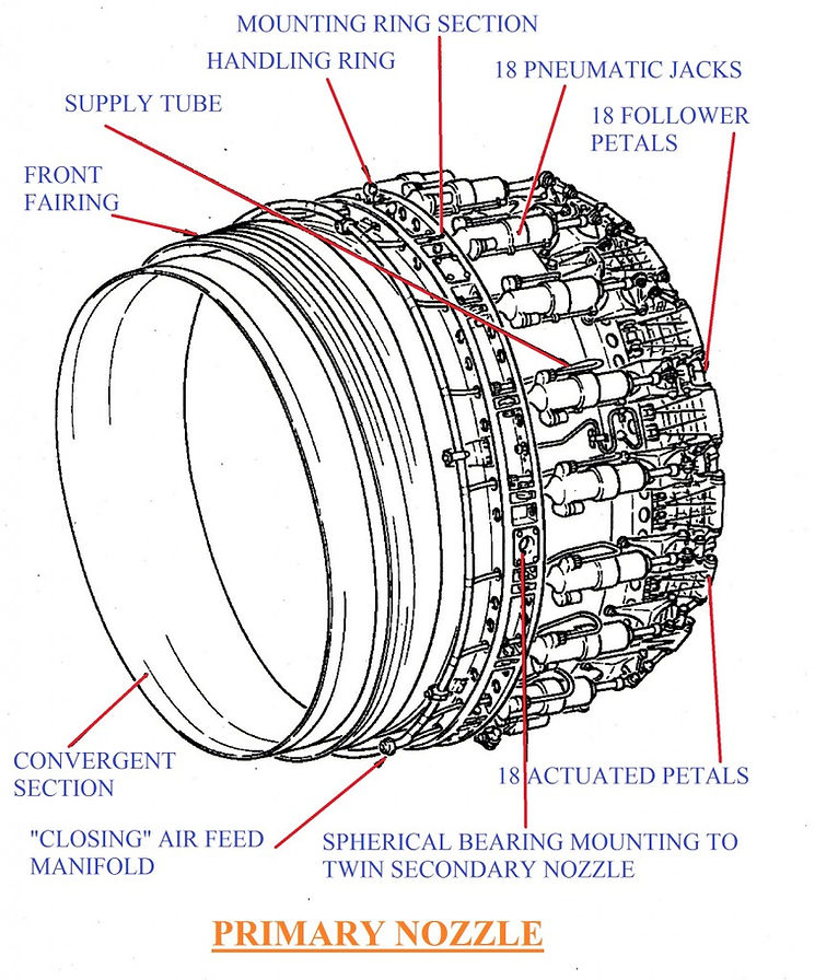
FIGURE 2
The mounting ring section is a one-piece, austenitic steel forging, which is ECM machined, which:-
Takes the loads which the 3 primary nozzle-to-twin secondary nozzle mounting pins transmit to it.
It includes the mounting points for the 18 pneumatic jacks and the air feed manifold.
It also takes the loads which the handling ring imposes on it during manoeuvring of the support ring assembly (See Fig.2, above)
The mounting ring is protected internally from radiated heat by a three part riveted heat shield. Each part of the heat shield is composed of quartz glass fibre sandwiched between two sheets of washed stainless steel.
The support ring assembly accommodates the primary nozzle area detection system. It is mounted on a support assembly which is fixed, at one end, to a yoke fitted to the mounting ring, and, at the other end, to a twin yoke.
-
The petals
The petals-in cast austenitic alloy-comprise two types:-
The actuated petal-hinged to 18 twin yokes fitted to the rear flange of the support ring assembly.
The follower petals, which are fitted and “float” between the actuated petals.
-
Pneumatic jacks.
The 18 pneumatic jacks are of the tandem mounted double piston type (See Fig. 4, below).
They are connected by 18 supply tubes and the manifold.
The body and the push rod of the jack are fitted with spherical bearing ends, which allow angular movement of the jack during operation. The jack body is thus fixed to the mounting ring by a pin, and the push-rod is attached to a lever by a threaded pin and nut.

FIGURE 3
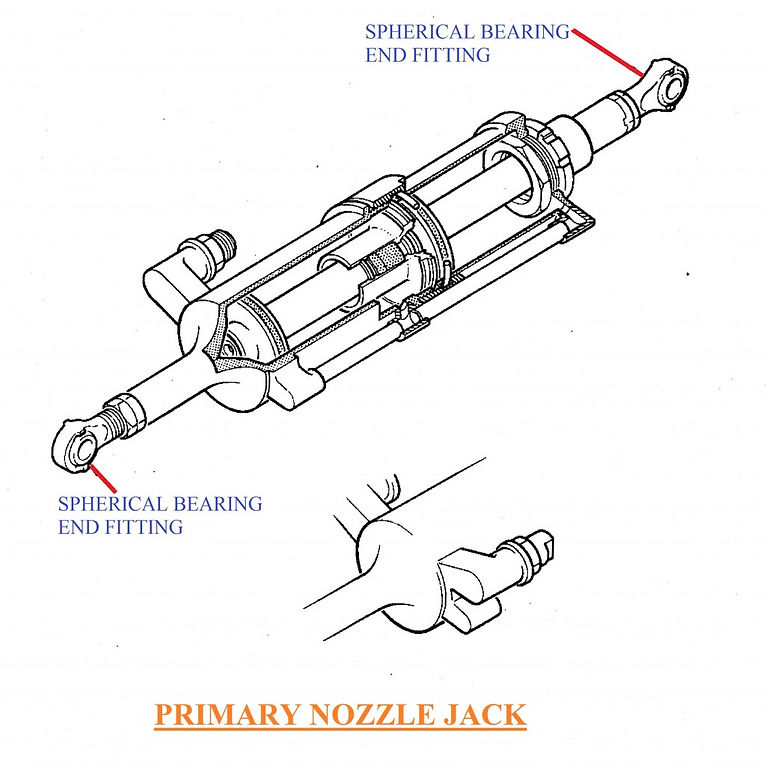
FIGURE 4
Operation
The outlet area of the primary nozzle is varied by the simultaneous action of the 36 petals (18 actuated, 18 followers) moved by the 18 pneumatic jacks. It is controlled by the P.N.C. (Pneumatic Nozzle Control Unit) fixed in the nacelle.
The jacks only act in the nozzle closing direction. The petals are driven open by the gas stream pressure.
Figure 5 below, shows the linage system to the petals. It can be seen that the control linkage itself ensures synchronisation of the movement of all the petals, since each jack is connected to two actuated petals and the movement is thus transmitted from one to the other.

FIGURE 5
The Secondary Nozzle
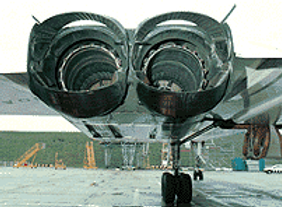
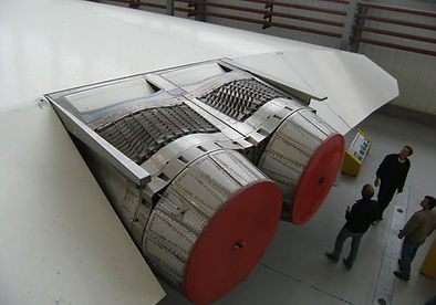
ABOVE: The production aircraft Secondary Nozzel.
RIGHT: The prototype aircraft Secondary Nozzel.
The production Concordes use the Type 28 Secondary Nozzle, as seen in the picture to the left. It’s an altogether larger and more robust assembly than the one used on the prototype Concordes, as seen in the picture below. It has to be: fully 29% of total thrust bears down on these surfaces during supercruise. Bucket drive is affected via an air motor and ball-screw jacks, operating to a Mach number signal.

Three completely different tasks are performed by the Type 28 Secondary Nozzle:
(1) At all times below Mach 0.55 – on the ground, take-off and initial climb – the buckets are set to 21 deg., forming a ‘jet-pump’ gap at the nacelle trailing-edge. The high speed jet exiting from the primary nozzle draws-in atmosphere air from above and below the nacelle to eradicate a source of base drag that would otherwise exit between the nozzles.
(2) Once the secondary air doors have opened and a strong secondary flow has been established, base drag no longer exists, thus the buckets are opened progressively to 0 deg. by Mach 1.1, to form a divergent duct. The fully established secondary flow and buckets at 0 deg. work together to shape and control the jet efflux, to optimise thrust in supersonic flight.
(3) For reverse thrust on landing, the buckets close across the jet-pipe deflecting exhaust flow forwards. The inboard engines may be set to idle reverse in flight to increase rate of descent.
The twin secondary nozzle assembly (See figure 1, below) was developed by SNECMA to equip the power units of Concorde, it fulfils two main functions:-
(1) A convergent-divergent secondary nozzle function
(2) A thrust reverser function for deceleration in flight and during landing.
In addition, the thrust-reverser system contributes to the achievements of optimum performance in all flight configurations.
General Characteristics
The twin secondary nozzle system assembly weighs approximately – 2,535lb (1150kg)
Its dimensions are:-
Length – 82.7 in (2100mm)
Width – 110.0 in (2800mm)
Height – 61.0 in (1550mm)
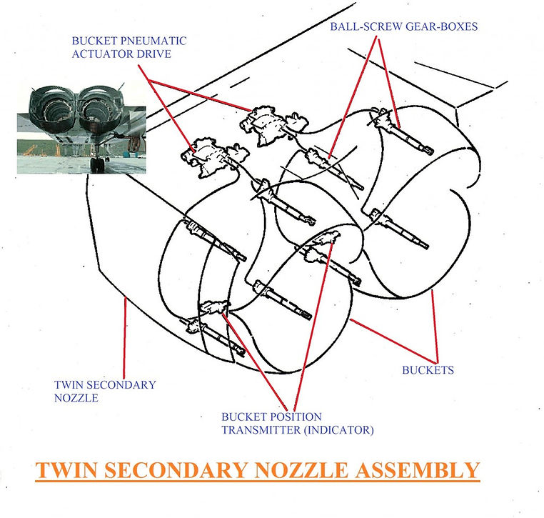
FIGURE 1
General Description of the Twin Secondary Nozzle
The twin secondary nozzle is a monobloc assembly which constitutes the final section of the engine nacelles. The two twin secondary nozzles fitted to the aircraft are not identical due to the geometry of the nacelles, between two adjacent engines and the aircraft axis of symmetry.
The Functions of the Secondary Nozzle
The secondary nozzle assembly has the following functions:-
(1) To support the primary nozzles
(2) To support the buckets and their actuator system
(3) To ensure continuity of the lines of the nacelle
(4) To channel the secondary air during straight-jet operation and to control the expansion of gas issuing from the primary nozzles.
(5) To transmit loads imposed on the primary and secondary exhaust systems to the air frame.
Attachment of the Secondary Nozzle Assembly
The connection of the secondary nozzle to the nacelle is isostatic, and comprises of 4 attachment points (SEE FIGURE 2, BELOW).
(1) Two clevis attachments on the outer walls, carrying loads in directions X and Z
(2) A clevis attachment fitted to the upper section of the central wall, carrying loads in direction Y. This attachment can also take loads in direction X, in the event of failure of one of the outer wall attachments, or the lower attachments.
(3) A clevis attachment on the lower part of the central wall, carrying load in direction X and also capable of taking load in direction Z in the event of one of the outer fixation points.
FIGURE 2

The Composition of the Secondary Nozzle
The secondary nozzle has the form of a rectangular prism with two cylindrical bays in the lengthwise direction.
It comprises basically of:-
- Three walls forming a cell (a central wall and two outer walls) parallel to each other and inter connected by upper and lower frames.
- Internal and external skin panels rigidly fixed to the framework of the twin secondary nozzle.
- Removable panels which form, in effect, the hot sections of the twin secondary nozzle.
- Access doors for the various actuator system elements, and for endoscope inspection of the structure.
- Parts for the attachment of the accessories mounted on the secondary nozzle.
Description of the Frame-work - (SEE FIGURE 3, BELOW)
FIGURE 3

The Outer Walls
They comprise two horizontal beams (1 and 2) inter-connected by stringers (3) riveted to the beams.
The beams which transmit load to the airframe, are machined from-solid-sections welded together.
At the rear of these beams are situated the bucket hinge points (4).
The yokes (5) for fixing the nozzle to the nacelle are situated towards the top at the extreme front of the structure.
Towards the front, and near the horizontal centre line of the outer walls is situated a housing (6) for the primary nozzle mounting pin.
The Central Wall
The technology of the central wall is similar to that of the outer walls. The beams carry the bucket hinge points at the rear, and the nozzle-to-nacelle fixation points at the front.
The stringers connecting the beams are fabricated from various materials; they are machined-from-solid-sections-brackets-honeycomb sections.
Upper and Lower Frame-work
These form the connection between the wall frames. They comprise machined-from-solid sections that are riveted together.
In addition, the frames carry the upper (8) and lower (9) housings for the primary nozzle fixing pins.
Description of the Skin Panels
The inner and outer skins are made from stainless steel honeycomb sheet. Most of the panels are riveted to the frame-work, imparting a high degree of rigidity to the assembly, others are removable, such as:-
(A) The convergent panels in austenitic alloy, which form the convergent section of the secondary nozzle.
(B) The divergent panels in austenitic alloy, which form the divergent section of the secondary nozzle.
(C) The shields, in stainless-steel honeycomb sheet, which provide thermal protection for the rear-end frame-work of the secondary nozzle when in “reverse thrust” configuration.
(D) The fairings, in stainless-steel honeycomb sheet, which form the extension of the side-walls.
(E) The access doors to the various elements of the bucket actuator system, which are located as follows-
At the top
At the front, two central doors giving access to the pneumatic motors.
At the rear, one central door giving access to the bucket central screw gear-boxes and the bucket crossfeed isolation valve.
At the rear, two side doors giving access to the bucket side screw gear-boxes.
At the bottom
At the front, two central doors giving access to position indicators.
At the rear, one central door giving access to the bucket central screw gear-boxes.
At the rear, two side doors giving access to the bucket side screw gear-boxes.
(F) The covers blanking the twin secondary nozzle endoscope inspection holes. The position of these inspection holes is given in FIGURE 4 below
Description of items for fixing the Primary Nozzle and the Buckets
FIGURE 5

Attachment of primary nozzles
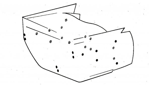
Each of the two primary nozzles is fixed to the twin secondary nozzle by 3 pins (SEE FIGURE 5, ABOVE). These pins (1), in high-temperature alloy, fit at one end, into housings integral with the secondary nozzle frame-work. The other end, covered with a sleeve, fits into the inner ring of a spherical bearing, fixed to the primary nozzle support ring. The pins are retained in the axial direction by the components – cup-washer (2) spherical end stop (3) dogged washer (4) retained by the keep plate (5). A cover (7) blanks the recesses containing the pins and locking system. On the upper and lower pins, the cover (7) is fitted with a spacer (6) Bucket Attachment
FIGURE 6
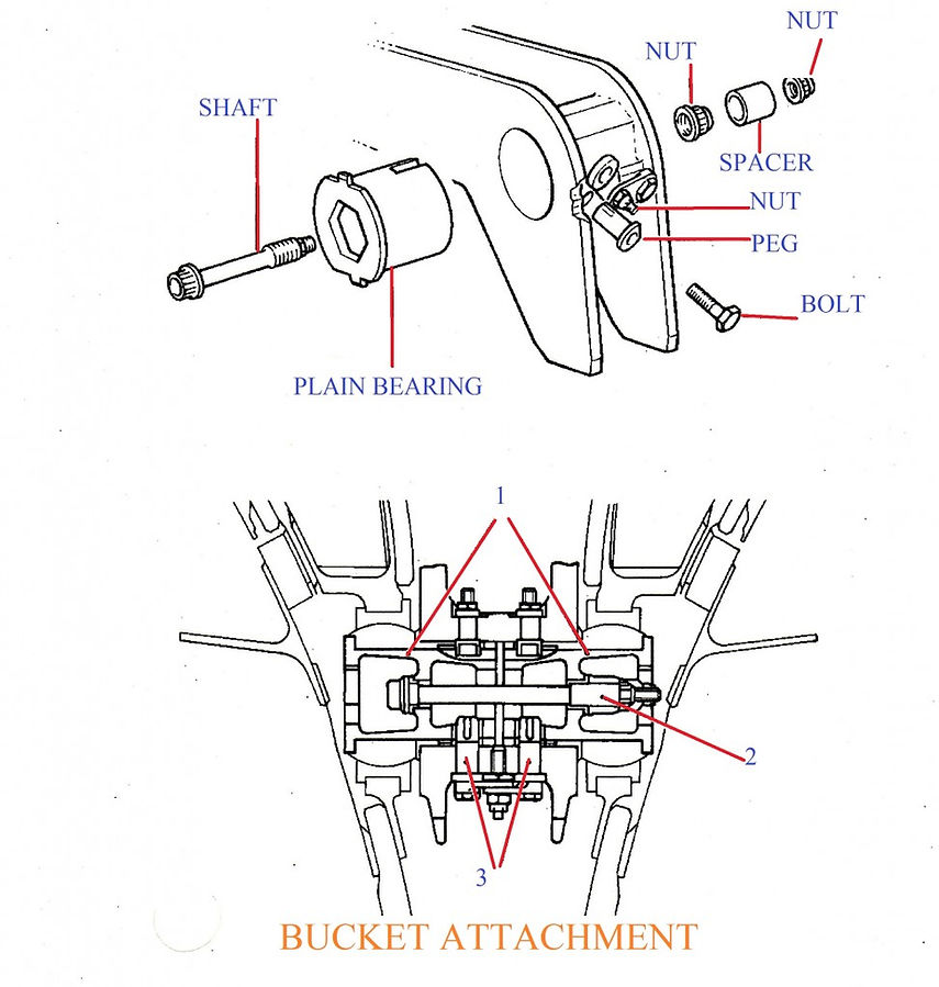
Each twin secondary nozzle is fitted with four buckets, each of which has two hinged points with the secondary system. These hinge points are situated at the rear of the central and side wall members of the twin secondary nozzle assembly. The mounting is affected by a plain bearing fitted into the inner ring of the spherical bearing in the bucket. The plain bearing includes pegs which prevent the inner ring from the rotating. The risk of the plain bearing (1) becoming dislodged from their housings in the case of a failure of the shaft (2), lead to the introduction of a retaining device. This consists, basically, of a peg (3) for each plain bearing. The pegs (3) are fixed to the hinged bracket into which the plain bearing (1) are fitted, thus limiting their movement in case of a failure of the shaft (2).
Austenitic alloy deflectors are fitted to the inside of the buckets. During reverse thrust, these deflectors resist the ingestion of hot gas into the interior of the secondary nozzle. In addition they protect the bucket hinge points on the twin secondary nozzle.
The Operation of the Primary Nozzle Area Transducer Harness
FIGURE 7

Two harnesses (SEE FIGURE 7) are fitted to the secondary nozzle, and are located symmetrically about the assembly centre line. They are located in the lower forward part of the interior of the structure. One end of the cable exits in the forward part of the central wall, and is fixed by two bolts with a plate (1) and a bar. This end constitutes the harness frontier with the nacelle. The other end is attached to the nozzle area transducer fitted to the primary nozzle. The free section of the harness is supported by two half clamps (2) fixed to the bay wall.
The nozzle area transducer harness is itself composed of the following:-
A screened four-cored cable (3) with thermal-setting sleeves placed close to the connector at the end of the screening.
A receptacle (4) with four pins.
A movable four pin socket connector (5)
A protective sheath comprising a flexible sleeve (6) in stainless steel brazed to the movable connector.
Identify sleeves for each wire, yellow in colour and marked A, B, C, D, respectively.
ACCESSORY ATTACHMENT PARTS
FIGURE 8

Bucket Pneumatic Drive motors (SEE FIGURE 8, ABOVE)
The bucket actuator drive motors (1) are located in the upper forward part of the twin secondary nozzle; access is via the central doors. The motors are fixed to the structure at three points:-
Two rigid motor-to-structure mounting points (2)
One adjustable motor-structure mounting by means of tie-rod (3)
The P3 air feed for each bucket motor is affected by a tube which crosses the forward bulk head of the central wall, to which it is secured by a nut (5). The other end of the tube is fixed to a sing. Two covers (7) blank the tube (4) passage in the base of the housing. The connection between tube (4) and tube (8) mounted on the motor is effected by a telescopic tube (9), thus ensuring continuity of flow without imposing mechanical loads on the connection point. An exhaust duct (10) fixed to each motor, passes through the access door and allows exhaust air to escape to the outside of the structure.
Attachment of the nozzle ball-screw gear-boxes, and bucket position transmitters (indicators) (SEE FIGURE 9, BELOW).
FIGURE 9

Bucket ball-screw gear-boxes
Attachment of the bucket ball-screw gear-boxes (1), which there are eight, twin per secondary nozzle; i.e. two gear-boxes to move each bucket. The end fitting (2) of the gear-box fits into a yoke on the bucket. The other end (i.e. reduction gear-box end) carries a yoke (3) which is an rigidly mounted on the secondary nozzle. The bracket (4) carries a peg which fits into the gear-box yoke (3) and which, with anti-rotation brackets (5), engaged into the bucket yoke, resists any reaction torque resulting from the operation of the nut/screw system.
The hinge between the bracket (4) and the yoke (3) includes a spherical bearing crimped into the bracket.
There is bucket position transmitters (indicators) fitted, which there are two per twin secondary nozzle. They are located in the lower, forward part of the structure. The position transmitters (1) are three-point mounted by two removable supports (2) and a fixed support (6). The transmitter trunnions (4) fit into spherical bearing (3), attached to these supports.
FIGURE 10

BUCKET CROSFEED ISOLATION VALVE
The isolation valve (1) (SEE FIGURE 10, ABOVE) is located in the upper central part of the secondary nozzle. It is mounted on a bracket which pivots on a flanged shaft (3) rigidly mounted on the secondary nozzle structure. The isolation valve is fitted into the tube connecting the two P3 air feeds to the bucket motors. Thus the tube is supported.
ELECTRICAL HARNESS
On each secondary nozzle are fitted two electrical harnesses which connect the various accessories fitted to the nozzle. These harnesses comprise of a junction box fixed inside the bucket motor housings, from this junction box, two looms go to the following, one to the bucket motor, and the other to the bucket position transmitter (indicator). The looms are supported by clips and are lead through the structure inside a metal tube fixed to the structure. The outlet connectors from the junction boxes form the harness frontier between the secondary nozzle and the nacelle.
The electrical harness for bays 2 and 4 include a third loom for the isolation valve.
OPERATION OF THE TWIN SECONDARY NOZZLE ASSEMBLY
The secondary nozzle assembly embodies the basic twin secondary nozzle, the reverse buckets and part of the whole reverse bucket control system. I will now attempt to offer you the reader a short description of the whole control system…
Composition of the reverse bucket control system
FIGURE 11

This system embodies electro-pneumatic pieces of equipment; the logic diagram in (FIGURE 11) will show you this. The equipment is as follows….
The reverse command system
This system is remotely installed and is thereby not part of the secondary nozzle assembly. It is composed of:-
(A) The A.D.C. (Air Data Computer) which deliverers an electrical signal proportional to the aircrafts Mach number.
(B) The N.A.S.U (Nozzle Angle Scheduling Unit) this generates a signal S1 = f (Mach) versus the pre-selected modulation law (Ref. to FIGURE 12 BELOW).
(C) The N.T.R.C. (Nozzle and Thrust Reverser Controller). This compares the feedback signal proportional to the position of the buckets, with the thrust reverse command signal S1. it amplifies the error signal to command the bucket pneumatic drive actuator operation.
FIGURE 12

The reverse actuating system
This system is part of the twin secondary nozzle assembly. It is composed of:-
(A) The bucket pneumatic drive actuator, which itself incorporates the following-
An air motor
An electro-magnetic control valve, which supplies a pneumatic signal as a function of the error signal.
An L.V.D.T. (Linear Variable Differential Transformer) which, from a duplication of the pneumatic drive actuator position, provides a feedback electrical signal to the N.T.R.C.
Verious pneumatic servo-control systems.
(B) The flexible shafts which transfer the air motor power output to the bucket ball-screw gear-boxes.
(C) The ball-screw gear-boxes which actuate the buckets.
(D) The bucket position transmitter (indicator), integrated in the transmitter train, which sends signals about the bucket positions to provide for the indication and safety functions.
(E) The bucket cross-feed isolation valve which allows in-flight thrust reverse on the two inboard engines.
Operation
The twin secondary nozzle assembly and the bucket control system provide for the following:-
(A) Specific, major functions:-
-Modulation of the twin nozzle exhaust area
-Thrust reverse operation
(B) Secondary safety functions:-
-Automatic return of engine to idle power setting (wind-down)
-Limitation of the bucket travel
(C) Indication functions for the flight crew information.
MODULATION OF THE TWIN NOZZLE EXHAUST GAS AREA
To optimize the powerplant performance, the secondary nozzle exhaust area is modulated versus the aircraft Mach number. The buckets, which govern the exhaust gas area, are servo-controlled in position by a regulation loop comprising the Nozzle and Thrust Reverser Controller (NTRC) and the bucket pneumatic drive actuator.
At any time, the NTRC compares the actual bucket position with the command signal delivered by the Nozzle Angle Scheduling Unit (NASU). The resulting error signal, if any, commands the pneumatic drive actuator to operate, thus causing the buckets to move towards the required direction (SEE FIGURE 13, BELOW) by means of the flexible shafts and of the bucket ball-screw gear-boxes.

THRUST REVERSE
Engine thrust reverse is applied on around during the aircraft landing roll or in case of aborted take-off in order to assist the aircraft braking; it is also used in flight to ensure a sufficient aircraft descent rate during the subsonic deceleration phase. In the two cases, the buckets are positioned at 73 deg. thus blocking the free passage for the exhaust jet while enabling the obtention of a negative thrust (SEE FIGURE 13)
On-ground thrust reverse mode
During the phase where the thrust reverse is operating, the bucket pneumatic drive actuator is controlled in open loop configuration. The reverse command signal, emanating from the relevant reverse lever, opens the regulation loop. The pneumatic drive actuator electro-magnetic control valve us then electrically supplied with a constant control current which is cause for the bucket actuation towards the 73 deg. angular position.
In flight thrust reverse mode: pneumatic cross-feed system
In- flight thrust reverse, used to increase the aircraft descent rate, is applied on the two aircraft inboard engine only.
At high altitude and with the engines at idle power, the air bleed pressure available from the HP compressor of the engines, taken individually, is marginal to ensure a suitable deployment of the buckets in the exhaust stream. Consequently, in order to obtain a higher pneumatic pressure, the actuating system of the inboard bay’s buckets are – during the buckets transit period – supplied via the cross-feed isolation valve by HP bleed air from the adjacent engine, the idle power of which is set at a higher level for the whole duration of reverse sequence.
Automatic return to idle power (wind-down)
The engine power rating is automatically re-set to idle in the two following occurrences:-
- Movement of the buckets beyond 45 deg. without having the thrust reverse selector beforehand.
- Movement of the buckets within 71 deg. when the reversed jet position is selected.
Thus function is achieved by means of micro-switches, the operating state of which is slaved to the bucket position (bucket position transmitter (indicator)) and to the pilot’s throttle lever configuration.
The resulting signal is then sent to the basic engine control amplifiers which in turn, govern the engine rotational speed.
Interlocking of the bucket actuating system
A shut-off valve located on the bucket pneumatic drive actuator air inlet system cut the air feed should an unwanted transit of the buckets beyond 27 deg. occur, notwithstanding the non-selection of the thrust reverse; the buckets are then interlocked in a position slightly higher th7 deg.
Indications
Some of the analogic and/or logic indications are conveyed back to the aircraft cockpit or to the 3rd crew member station and allow to visually check for nominal operation of the who system
Secondary Nozzle positions
Take-off position

At take-off they are close slightly, allowing air to be sucked in from outside for mixing with the exhaust. This reduces noise, as well as improving engine performance.

Supersonic cruise

During the climb they progressively open until, soon after passing Mach 1, they are acting as an expansion chamber.
Reverse thrust

The same system acts as a thrust reverser on all four engines on the ground, to assist Concorde with braking in the air the two inbound ones are used, to increase the rate of descent.

The intake and variable exhaust system are together responsible for a good deal of Concorde’s thrust development about half of the thrust at Mach 2 is due to their combined effect.