Explore the world of Concorde with Heritage Concorde
Concorde Visor Removal & Replacement
The Concorde visor is secured by bolts to a hydraulically operated mechanism that raises and lowers the visor on rails. It also has electrical connections for the visor window panel de-icing system. When removing and installing the visor, the nose must be fully lowered to give the visor maximum clearance with the windshield.

Equipment and Materials required for the task
Visor screwjack
Visor screwjack torque handle
Visors sling
Droop nose checking sling
Sling attachment bracket
Spring balance (2 ton)
Droop nose locking pin (2)
Nose actuator jack locking sleeve
Bolt extractor set:
-
Barrel
-
Body
-
Bolt
Torque spanner, O to 340 Lbf in (O to 3.85 mdaN) range
Circuit breaker safety clips
Locking wire, 0.028 in (0.71 mm) dia.
Hydraulic ground generation rig
Lifting equipment (SWL 700 lb (310 kg)

Required Preparation for Installation of the Replacement Visor

Prepare the replacement visor prior to installation:
Remove the visor seals
Remove the electrical wiring and clips from the old visor, carry out an inspection/check to ensure that they are serviceable and undamaged and fit them to the new visor. Connect the electrical plugs to the visor window panels ensuring that the plug and receptacle mating surfaces are clean and undamaged.
Remove the shims from either side of the visor index roller and set the eccentric shaft so that maximum clearance will be obtained between the roller and the visor locating fitting on the windshield (See picture 5 for reference). Ensure that the visor hooks are set to their lowest position on the serrated plates to give maximum clearance between the hooks and the stopping on the Locating fitting (See picture 5 for reference)

Preparation to Remove the Visor
If the nose is not in the 12-1/2 deg. position, ground electrical power will be required, once this is connected to the aircraft, the following procedure will need to be carried out:-
Pressurize the green and the yellow hydraulic systems using the aircraft ground hydraulic checkout system.
Operate the VISOR/NOSE normal control lever on the co-pilot’s dash panel to set the nose DOWN.
Fit the visor ground equipment screwjack:
Re-pressurize the green and yellow hydraulic systems by operating the manual pressure relief units Located in zone 151, and the pressure relief valves fitted to the base of the relevant hydraulic reservoir in zone 153.
Electrically isolate the visor and nose normal and standby controls by tripping the following circuit breakers
M11 on panel 15-215 ref. F8, and M12 and M13 on panel 1-213 ref. Q16 and Q17; next fit safety the clips.
Disconnect the electrical plugs from the normal and the standby selector valves (M45 and M51) in the equipment bay (zone 121).
Fit the screwjack
Fit the safety locking sleeves to the nose actuator jacks.
Electrically isolate the visor de-icing window panels by tripping the associated circuit breaker and fit the safety clips.
Disconnect the visor window de-icing electrical cables from the operating leg at the plug breaks UI035 and UI036 and P-clips.
Fit the visor sling
(a) Raise the visor to an approximately three quarters raised position using the visor screwjack and remove the access panels and glazing retaining bar to gain access to the visor slinging points.
(b) Fit the lifting bracket to the visor at the forward slinging point.
(c) Lift the sling into position using suitable lifting equipment and attach the sling to the visor.
(d) Operate the lifting equipment to take the weight of the visor.
Removal of the Visor
Disconnect the four bonding leads connecting the tops of the operating leg and the strut assemblies to the visor.
Disconnect the operating leg, the tracking legs and the struts from the visor. Use the extractor tool to withdraw the bolts where shown.
SUITABLE PRECAUTIONS MUST BE TAKEN TO AVOID DAMAGING THE WINDSHIELDS
Remove the visor, lowering it on to a suitable stand and detach the visor sling. Next refit the access panels and glazing bar at the visor slinging points.
Install the Visor
Ensure that the following conditions still prevail following the removal of the visor procedure:
(a) Hydraulic green and yellow systems off-loaded.
(b) Electrical safety precautions still in force.
(c) Nose Lowered to the 12-1/2 deg. fuL1.y down position and safety sleeves fitted to the nose actuator jacks.
(d) Visor screwjack fitted and holding the visor carriage mechanism just short of the fully raised position.
Fit the sling to the visor as shown in the picture below


PICTURE 4. Above
Now using suitable lifting equipment, raise the visor into its position.
Fit the visor to its mechanism
(a) Secure the operating leg to the visor. Torque load the left hand nut to between 320 and 340 Lbf in (3.55 and 3.78 mdaN), and the right hand nut to between 140 and 155 I.bf in (1.58 and 1.75 mdaN). Secure each nut with a split pin.
Connect the bonding leads.
(b) Secure the tracking Legs to the visor (Details B and C in the picture 4 above). Torque load the outboard bolt of each leg to between 140 and 155 lbf in (1.58 and 1.75 mdaN) and the inboard bolt to between 320 and 340 lbf in (3.55 and 3.78 mdaN). Secure each nut with a split pin.
(c) Secure the strut assemblies to the visor (Detail D in the picture 4 above). Torque load each nut to between 80 and 90 lbf in (0.9 and 1.02 mdaN) and lock it with a split pin. Connect the bonding leads.
NOTE:
Ensure that the bush is in the strut fork end before connecting it to the visor and ensure that the fork end is visible through the inspection hole in the strut.
Remove the sling and the lifting bracket from the visor and refit the access panels and forward glazing retaining bar that covers the sling attachment joints (See picture 3 for reference)
Remove the safety sleeves from the droop nose actuator jacks.
Remove the screwed plugs from the sling attachment bracket point and fit the bracket. Attach the checking sling, complete with spring balance, and with it raise the nose to the fully up position. Fit the locking pins to the droop nose.
NOTE:
The weight on the checking sling must not exceed 1070 Lb (485 kg)
Raise the visor to the fully-up position using the screwjack and check that the metal. to metal gap between the rear edge of the visor and the fuselage is 0.22 in to 0.30 in (5.58 to 7.62 mm), and that between the visor and the nose fairing is 0.23 in to 0,29 in (5.84 to 7.36 mm). If necessary, position the visor to obtain these clearances, by adjusting the visor unlock rollers.
Check that the visor engages correctly with the visor locating fitting on the windshield by opening the hinged side window panels in the visor and checking that with the visor fully up there is a mean gap of 0.001 in to 0.010 in (0.025 to 0.254 mm) between the visor hooks and the stop-pin on the locating fitting
(See picture 5 for reference). If the gap is outside the Limits, adjust the visor locating fitting.
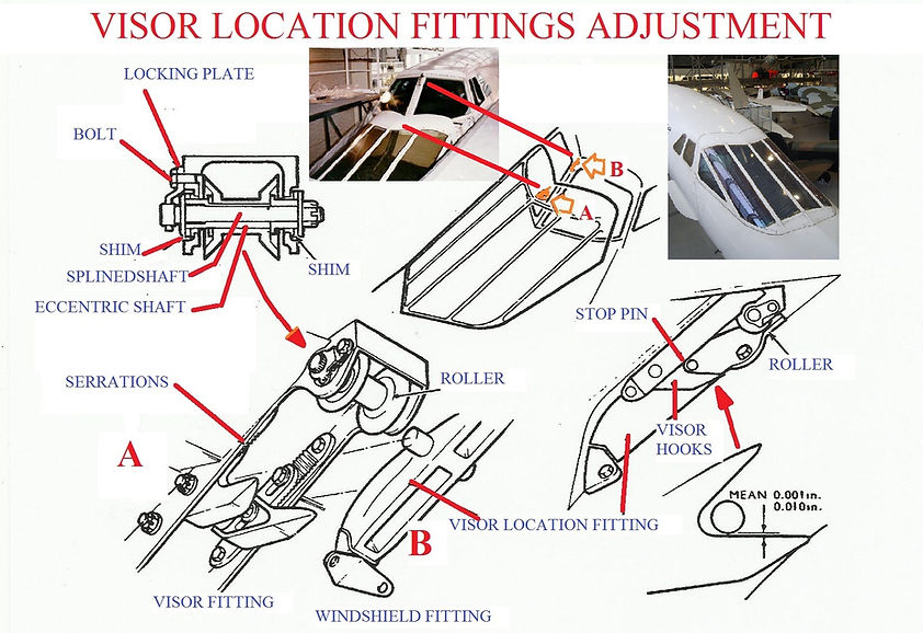
PICTURE 5 Above
Installation of the Replacement Visor
Connect the visor window de-icing electrical cables at the plug breaks UI035 and UI036 on the operating leg, and secure the cables to the leg with P-clips.
Remove the visor screwjack.
Remove the checking sling and bracket from the droop nose and refit the screwed plugs to the bracket attachment holes.
Reconnect the electrical plugs to the normal and standby selector valves in the equipment bay.
Reset the visor and nose control, and visor window panel de-icing circuit breakers. Function test the visor window panel de-icing system
Remove the locking pins from the droop nose.
Carry out the visor and droop nose operational test and Adjustment/Test.
