Explore the world of Concorde with Heritage Concorde
Concorde Olympus 593 MK.610 Engines
The Concorde Olympus 593 Mk 610 engine, remain to this day the most efficient jet engine in the world at Mach 2, where thermal efficiency in concerned. But at lower speeds the engines consumes fuel at a massive rate.
Subjects included in this section are as follows-
Concorde engine Combustion Chamber/Turbines/Engine Control/Power Control/Mass Control/Fire Supression/Support Structure/Reheat


For Concorde to be economically viable, it needed to be able to fly reasonably long distances, and this therefore required high efficiency. For optimum supersonic flight, turbofan engines were considered, but then rejected, this was due to their large master cross-section which would cause excessive drag. Turbojets were found to be the best choice of engines for Concorde. The quieter high bypass turbofan engines such as those which are now used on the Boeing 747s could also not be used. The engine chosen was the twin spool Rolls-Royce Olympus 593, a version of this Olympus engine had originally been developed for the Vulcan bomber, and then developed into an afterburning supersonic engine for the BAC TSR-2 strike bomber and then in association with the French company Snecma Moteurs , this had been adapted for Concorde, with the final version fitted to the production aircraft known as the 593 mk610.
The Olympus 593 Mk 610 engines that were installed in all the production Concordes remain to this day, the most efficient jet engines in the world at Mach 2, as far as thermal efficiency is concerned. They may be efficient at Mach 2 and above, but at slower speeds it uses fuel in a most inefficient way, so this required a minimum amount of low flying speeds for Concorde.
The original design for the Concorde Olympus 593 reheat system was carried out by SNECMA, but due to them getting into all sorts of trouble during the project with the fuel injection system and the flame stabilisation, Rolls-Royce got involved and baled them out, and the re-heat system became a Rolls-Royce/ SNECMA design. (The core engine was a 100% Rolls Royce design, with no French input whatsoever. However some engine sub-assembles were manufactured by SNECMA).


Hear the sound of 4 olympus engines, startup and shutdown

THE CONCORDE 593 ENGINE VARIANTS
-
593 – Original version designed for ConcordeThrust : 20,000 lbf (89 kN) dry / 30,610 lbf (136 kN) reheat
-
593-22R – Powerplant fitted to prototypes. Higher performance than original engine due to changes in aircraft specification.Thrust : 34,650 lbf (154 kN) dry / 37,180 lbf (165 kN) reheat
-
593-610-14-28 – Final version fitted to production ConcordeThrust : 32,000 lbf (142 kN) dry / 38,050 lbf (169 kN) reheat
Specifications (Olympus 593 Mk 610)
General characteristics
-
Type: Turbojet
-
Length: 4039 mm (159 in)
-
Diameter: 1212 mm (47.75 in)
-
Dry weight: 3175 kg (7,000 lb)
Components
-
Compressor: Axial flow, 7-stage low pressure, 7-stage high pressure
-
Combustors: Nickel alloy construction annular chamber, 16 vaporising burners, each with twin outlets
-
Turbine: High pressure single stage, low pressure single stage
-
Fuel type: Jet A1
Performance
-
Maximum Thrust: wet: 169.2 kN (38,050 lbf) dry: 139.4 kN (31,350 lbf)
-
Overall pressure ratio: 15.5:1
-
Specific fuel consumption: 1.195 (cruise), 1.39 (SL) lb/(h·lbf)
-
Thrust-to-weight ratio: 5.4
Control system
-
World’s first FADEC control system
Jetpipe
-
Straight pipe with pneumatically operated convergent nozzle
-
Single ring afterburner
-
‘Eyelids’ which act as variable divergent nozzles/thrust reversers


DESIGN AND DEVELOPMENT
The Olympus 593 project was started in 1964, using the BAC TSR-2’s Olympus 320 as a basis for development. Bristol Siddeley of the UK and Snecma Moteurs of France were to share the project. Acquiring Bristol Siddeley in 1966, Rolls-Royce continued as the British partner. The early stages validated the basic design concept but many studies were required to achieve desired specifications, e.g.
-
The critical factor – fuel consumption
-
Pressure Ratio
-
Weight/Size
-
Turbine entry temperature
Initially, engineers studied using turbojets or turbofans, but the lower frontal cross-sectional area of turbojets in the end was shown to be a critical factor in achieving superior performance. The competing Russian Tu-144 initially used a turbofan, but quickly changed to a turbojet with considerable improvement in performance.
Rolls-Royce carried out the development of the original Bristol Siddeley Olympus and engine accessories, while Snecma was responsible for the variable engine inlet system, the exhaust nozzle/thrust reverser, the afterburner and the noise attenuation system. Britain was to have a larger share in production of the Olympus 593 as France had a larger share in fuselage production.
In June 1966 a complete Olympus 593 engine and variable geometry exhaust assembly was first run at Melun-Villaroche, Île-de-France, France. At Bristol, flight tests began using a RAF Vulcan bomber with the engine attached to its underside. Due to the Vulcan’s aerodynamic limitations the tests were limited to a speed of Mach 0.98 (1,200 km/h). During these tests the 593 achieved 35,190 lbf (157 kN) thrust, which exceeded the requirements of the engine.
In April 1967 the Olympus 593 ran for the first time in a high altitude chamber, at Saclay Île-de-France, France. In January 1968 the Vulcan flying test bed logged 100 flight hours, and the variable geometry exhaust assembly for the Olympus 593 engine was cleared at Melun-Villaroche for flight in the Concorde prototypes.
At 15:40 on the 2nd March 1969 Concorde prototype 001, captained by chief test pilot Andre Turcat, started its first take off run, with afterburners lit. The four Olympus 593 engines accelerated the aircraft, and after 4,700 feet (1.4 km) of runway and at a speed of 205 knots (380 km/h), captain Turcat lifted the aircraft off for the first time.
.

Flight tests using a RAF Vulcan bomber with the engine attached to its underside.
BASIC BACKGROUND TO THE OLYMPUS 593-610
The production airliner Concordes are propelled by four Olympus 593 Mk.610 engines and together they produce 152,200 lbs of thrust at take-off and 27,160lbs of thrust during the cruise at 60,000feet. With their air in-take, re-heat and exhaust systems they are among the most technically impressive features of Concorde, but there are very noisy…….
Designing the engines for a Mach 2 supersonic aircraft such as Concorde, involves a lot of compromises. The first necessity is that they must work successfully in the cruise. This would require them to be narrow in cross-section, to minimize drag, add to that, they would also require a high exhaust velocity, otherwise the exhaust itself would tend to slow the aircraft. All of this means that Concorde required an engine with low by-pass ratio, a pure jet.

The disadvantages of this type of engine compared to that of a high by-pass ratio type, used on subsonic aircraft, is that it moves a smaller mass of air faster, unlike a high by-pass ratio that is comparative quiet. As a major component of aircraft noise comes from the mixing of the exhaust with the static air outside, a sort of tearing effect, the disadvantages of this pure jet type of engine used for Concorde starts to become obvious, but there was no other choice.
The Rolls-Royce (originally Bristol Siddeley)/Snecma Olympus 593 Mk.610 engines that are fitted to Concorde were at first called the Olympus 593B (B for big) and are a highly developed version of the Bristol-Siddeley Olympus 593D (D for derivation) the original Concorde engine and the first civil Olympus. The 593D is, in turn , a development of the Olympus 320 for the TSR2, the successor to the 201 and 301 series engines used in the Vulcan bombers this generated 11,000lbs of thrust.
The reason for the changed from the 593D to 593B was that when the Concorde specifications were upgraded to improve the range, in 1963, the increased take-off weight demanded a 12 per cent increase in thrust. This could have been obtained by development of the 593D, but it was decided that it was too early in the engine’s life to make such a large redesigned in its long term development potential. Therefore the engine was redesigned as the 593B, with new compressors and turbines. . Rolls-Royce provided the development of the Olympus engines while SNECMA developed the exhaust and re-heat system. On the prototypes this powerplant system was upgraded to generate 33,000Lbs of thrust and by the time it was fitted to the production aircraft, 38,050Lbs were available

The Olympus engines used on the prototype Concorde’s,were an axial flow twin spool engine with a can-annular combustion chamber. But one problem with this engine was the exhaust smoke; the Prototype Concorde’s exhaust smoke was horrendous. This therefore required a change from the can-annular combustion chamber to an annular, vaporising type. This cured the smoke, but the vaporisers kept falling off with regular monotony.
Each spool carries seven compressor stages and one turbine, the low pressure shaft running inside the high pressure shaft. The low pressure spool is carried in three bearings: a roller bearing mounted in the boss of the in-take casing, a twin-row ball thrust bearing in the intermediate casing which connects the two compressor casings and a roller bearing at the rear of the low pressure turbine. The high pressure spool is carried in a second twin-row ball thrust bearing in the intermediate casing and a roller bearing in the compressor inlet guide vanes, mounted in the intake casing, are of fixed incidence and tangential layout.
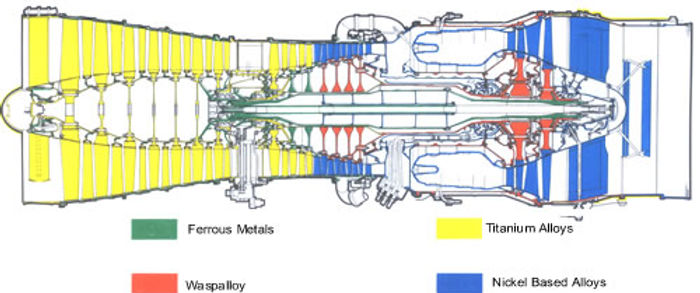
The blades and discs of the low pressure compressor and of the first stages of the high pressure compressor are made of titanium, to withstand the high temperatures to which they will be subjected during supersonic cruising and possible damage from any foreign objects; in the rear stages of the high pressure compressor, Nimonic 90 was used because of the even higher temperatures. At Mach 2 cursing the low pressure inlet temperature would be 127C. Both compressor casing are steel.
The high pressure turbine rotor and stator blades are vacuum cast. They are air cooled on all engines and on the production engine the low pressure turbine rotor and stator blades were cooled also; the latter are forged and vacuum cast respectively. At supersonic speeds when the air approaches the combustion chamber is very hot due to the high level of compression of 80:1.

Two Concorde Olympus 593 MK.610 engines
Nimonic 90 – Nickel-Chromium-Cobalt Alloy
Nimonic 90 is a Nickel-Chromium-Cobalt alloy being precipitation hardenable, having high stress-rupture strength and creep resistance at high temperatures up to about 950°C (1740°F). It is widely used and a well proven alloy in high temperature conditions.
The combustion chamber contains eight flame tubes which are mounted between the compressors delivery casing and the first stage high pressure stator ring. The latter, which has to withstand temperatures of up to 1148C, is cooled by Air trapped from the high pressure compressor at up to 560C and allowed to escape into the gas stream through slots machined in the trailing edge of the blades
Fuel is injected through a Simplex air-spray burner in the head of each flame tube and there are two igniters. Fuel flow is looked after by the electro-mechanical engine control system, the Ultra electronic throttle and fuel control system. This incorporates a 6A00 electric throttle, acceleration control, engine speed control, turbine entry temperature limiter and a magnetic computer unit. There is an over-speed governor for each fuel pump, but these only come into operation if a fault in the electrical system allows the turbine speed to rise above predetermined limits. The control system is analogue and control of it by the pilot is very straightforward, although, due to automation, detailed examination indicates a very complicated arrangement. The pilot has the ability to select the mode in which the engine operates by a single switch per engine –take-off, climb and cruise.
The oil tank is mounted on the portside of the low pressure compressor casing and supplies the pressure pump, which in turn feeds the main bearing through calibrated orifices. Sumps under the intermediate casing collect the oil by gravity drainage and the scavenge pump returns it to the tank through the fuel-cooled oil cooler.
On each of the four engines, are mounted two gearboxes, one for airframe accessories and one for engine accessories, both driven from the high pressure compressor drive shaft through the intermediate casing. Each of the former drives one or two hydraulic pumps (this is according to engine position) and a constant speed unit which drives a constant frequency a.c. main generator. Each of the latter drives a variable stroke high pressure fuel pump, a centrifugal low pressure pump and oil pumps.
THE COMBUSTION CHAMBER
Air flows directly from the HP compressor to the combustion chamber where the big challenge is to separate-off exactly the right amount of air to provide the correct mixture strength for complete and efficient combustion, and to slow down that portion of the air so that it doesn’t keep blowing the flame out. The rest of the air, and it is a substantial amount, is a cooling medium, carefully channelled to protect the walls of the chamber from the direct heat of combustion. It is the oxygen content of this airflow that enables reheat fuel to burn in the jet pipe.
It will be recalled that Concorde prototypes generally displayed a bit of a smoky exhaust. Which was down to incomplete combustion and was a waste of potential thrust, but the Olympus was derived from a military engine, where the function may have overridden friendliness.
There was always right from the start the plan to supply a totally new combustion chamber, but this did not arrive until 1970, and was the penultimate evolution of the Olympus engine, the 593-602. Prior to the change, fuel/air mixing had taken place in eight separate but interlinked chambers. Post-modification, there was but one large annulus, a cylinder within a cylinder, if you like, and inside sixteen twin-armed vaporisers spraying upstream against the gas flow. Rather than simply providing a highly atomised spray, the vaporisers sat far enough into the combustion chamber to be raised in temperature sufficiently to vaporise the fuel, providing highly efficient, smoke-free combustion, but extremely vulnerable to erosion, burning and cracking, alleviated to some extent by a changer from fabricated to cast vaporisers.
The annular combustion chamber was initially a great success, achieving all that was expected of it, but as engine operating hours built up after Concorde’s entry into airline service, the extreme conditions within the chamber took their toll. Splits, tears, burning and erosion of the chamber walls and fractures of the fuel vaporisers were detected by borescope inspections and in-flight analysis. During this period, maintenance engineers honed their pit-stop skills to the point where a complete engine change plus the attendant ground-run test could be wrapped-up in one eight-hour shift.
Development, however, never stands still: a revised annular chamber featuring anti-corrosion ceramic plating, better cooling and more efficient combustion appeared in 1981; it was good enough to see Concorde through its 27 years of airline service.
THE TURBINES
The turbines and the major controlling parameter – Turbine Entry Temperature TET has always been dependent upon metallurgy. Only the very best of super-alloys can withstand the continuous battering from the 1,000C plus, sonic velocity gas stream. Strength, heat resistance and immunity to exotic forms of corrosion are prerequisites. The HP turbine and its ring guide vanes bear the brunt of this onslaught. HP turbine blades have eighteen cooling holes drilled top and bottom, this is a technique developed to provide cooling passages for guild vanes and blades alike, using air bled from HP compressor fifth stages as the cooling medium – if 1,450C air can ever be termed a cooling medium! By this means TET was raised to 1,450C.
Turbine cooling air temperature, as a measure of turbine health, is sensed at two points between the HP and LP turbine and indicated on instruments at the flight engineer’s position on the flight deck. Normal super-cruise value would be around 550C, with a warning triggered at 640C requiring an engine shut down to prevent further deterioration. Exhaust Gas Temperature (EGT) and a jet-pipe pressure (P7) are both measured at position downstream to the turbines and displayed at the forward engine instrument panel and the flight engineer’s position respectively.
The Olympus engine combustion chamber is made from the material called Nimonic 263, which is described as nickel (47%), chromium (20%) and cobalt (20%) alloy. It has in the mix varying percentages of carbon, silicon, manganese, sulphur, aluminium, titanium, boron, copper, iron and lead with a dash of silver (0.0005%) and a hint of bismuth at 0.0001%; each element making its contribution to life in the ‘hot lane’
OILS & BEARINGS
The two main rotating assemblies are supported by five bearings – roller, ball, roller, roller – front to rear. The LP spool has a roller bearing in front of the compressor and the thrust bearing (ball) behind, with a roller bearing to support the turbine end, whereas the shorter HP spool runs on a thrust bearing in front of the compressor and a roller in front of the turbine.
The five main bearings, together with all accessory gears and drive bearings are lubricated by a single oil pressure pump set at 26psi. Five scavenge pumps direct return oil. Through fuel-cooled oil cooler, back to an external tank attached to the LP compressor casing, LH-side.
The oil tank contains 16 US quarts; total system content is 26 US quarts. Replenishment access is via a small hinged panel at the forward end of the main engine door. A special hand pump gun or dispenser must be used; a ‘fill’ connection and overflow connection are located at the tank base. There is no gravity top-up facility. For a complete oil change, oil may be drained through the ‘fill’ connector. The only oils/lubricants that could be used for the Olympus 593-610 were:
LUBRICANT – ‘A’ / SPECIFICATION – D.E.R.D.2497 – Iss.3
Esso ETO25
Mobil RM 193A-3
Shell ASTO 555
( Shell ASTO 555 USA blended must me marked D.E.R.D.2497 on the container)
Royco Turbine oil 555
Castrol 599
LUBRICANT – ‘B’ / SPECIFICATION – D.T.D.806B
AeroShell grease 8
Rocol Aerospec 305
LUBRICANT – ‘C’ / SPECIFICATION – MSRR4008
Rocol 251T
LUBRICANT – ‘E’ / SPECIFICATION – MSRR4008
Dentoil 900
LUBRICANT – ‘E’ / SPECIFICATION – MSRR9295
Turbo 10
LUBRICANT – ‘G’ / SPECIFICATION – D.T.D.900/4980
Rocol G576 (Formerly Foliac G576)
Polybutylcuprysil (grease)
LUBRICANT – ‘L’ - Never-seez aerosol spray NSN-16A
LUBRICANT – ‘M’ - Molycote G
LUBRICANT – ‘R’ - Rocket W.D.40
LUBRICANT – ‘S’ / SPECIFICATION – AIR 4247 (D.T.D.392B)
AeroShell compound 08
Total 4247
Nyco GA.47
LUBRICANT – ‘T’ – Guardian Chain Lubricant 1
But the different oils could not be mixed in the same tank. Engine oil pressure, temperature and contents are displayed at the flight engineer’s position
ENGINE CONTROL
The engine is controlled by a duplicated analogue electronic system; Main and Alternate, used turn and turn about. Each system can be divided into two parts: (1) the conventional fuel injection control that responds to throttle lever input to set the required fuel flow; (2) the networks that vary the primary nozzle area to control jet-pipe pressure, thus matching N1 to N2
ENGINE NACELLES

Concorde has two engine nacelles; each one accommodates two engines and is divided into two structurally independent parts, consisting of air-intakes and engine bays. There is an extension of the engine bay which incorporates the secondary nozzles. The intakes and engine bays are attached to the wing by flexible joints which ensure the complete sealing and continuity of form.

This picture shows the engine located within its engine nacelle, in the foreground its possible to see the air intake system ramps, further information regarding this system can be found under the section Air Intake System.
Picture copyright Stephen de Sausmarez & Heritage Concorde.
POWER CONTROL
At the simplest level, the throttle lever sets power: its position is signalled electrically to each Engine Control Unit (ECU). The ECU mixes throttle lever position with engine and atmospheric data to output a drive to the fuel throttle valve. Additional circuits control engine acceleration and prevent exceeding maximum and minimum limits
MASS FLOW CONTROL
Also contained within each ECU is a set of ‘schedules’, basically electronic graphs that output a drive signal to the primary nozzle to facilitate matching of LP and HP rpm to deliver maximum air mass flow, whilst keeping clear of surge, at all conditions. There are four ‘schedules’, selected either manually or automatically, according to phase of flight.
FIRE SUPRESSION
Being the first of a new generation of aircraft, the constructors have spared no effort to prove the integrity of each individual system and component on the aircraft, thus ensuring that the Concorde is the most thoroughly tested aircraft ever to enter airline service. This minute attention to detail is reflected in the design of the main powerplant fire protection systems.
In each engine bay there is a two-shot fire extinguisher and optical fire detector. If an extinguisher is used, the secondary air cut-off valve, the engine bay ventilation door and the tertiary air doors are closed. At the same time the heat exchanger inlet door, normally open either to atmosphere or to secondary air, splits under the action of a spring thus cutting off both air flows.
The closing of the secondary air cut-off valve causes the four fire doors to close also, because they are lightly spring loaded in the closing sense and are kept open only by the pressure of the secondary air flow. When closed they blank off triangular spaces between the compressor casing and the corners of the rectangular nacelle, completing a fire wall.
Two electrically separate fire wire loops, co-sited in a performed steel conduct, are located in the nacelle doors and around the engine, in normal operation both loops are in a circuit and both must detect a fire signal a warning. If only one loop is unserviceable, the good loop may be selected for single channel operation.

ENGINE BAY FIRE EXTINGUISHING SYSTEM:
1, Extinguisher bottle. 2, 1st shot pipe(engine2). 3, Directional flow valve. 4, 2nd shot pipe(engine2) 5, 1st shot pipe(engine1) 6, Fire valve pipe. 7, Pressure relief pipe. 8, Distribution pipe. 9, Spray nozzlw. 10, 2nd shot pipe(engine1) 11, Delivery pipe.
SUPPORT STRUCTURE
There are four engine suspension points on Concorde: two front suspension links attached to the top of the low pressure compressor casing and two main points, one on each side of compressor delivery casing. The front links are free to swing to allow for axial and radial expansion of the engine forward of the main points. The main points, which are conventional trunnion fixings, are connected to the wing structure by pin jointed vertical links and by engine thrust struts running forward and upwards. They take engine thrust loads, transverse and vertical loads and gyroscopic couples. One trunnion is fixed; the other is not restrained laterally to allow for the lateral expansion. There are four large non-structural access doors beneath each nacelle. All electronic connections are brought to a single panel above the compressor delivery casing.
.