Explore the world of Concorde with Heritage Concorde
Concorde Fuselage Windows
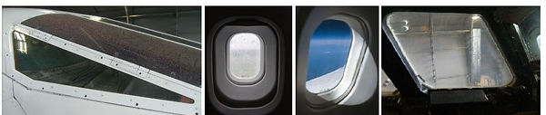
The external windows of Concorde must withstand a temperature variation of from approximately -50 deg C to approximately 117 deg C at the aircraft supersonic cruising speed. They are manufactured of the toughened glass, and are double-glazed with the exception of the flight deck windshield and visor panels. Cabin ventilating air is also supplied to the inside face of the main windshield.
Demisting of the double glazed windows is achieved by connecting the space between the panels either to a self contained dessicator system or to a continuous fresh air supply.
THE VISOR PANELS
Concorde has a retractable glass six panelled visor attach to the nose assembly forward of the flight compartment. This streamlines the windshield during supersonic cruise conditions. Detachable side panels give access to the underside of the glazed area allowing for maintenance and cleaning. The laminated glass visor windows are set in rubber seals in the visor frame, and are retained by glazing bars secured by titanium nuts and bolts. Each window carries a gold de-icing electrical heating element. Until the Space Shuttle flew, the visor glass panels were made of the strongest glass in the world.

THE FLIGHT DECK COMPARTMENT WINDOWS
The windows in the flight deck compartment comprise a two panel forward facing windscreen of laminated glass, and which have built-in electrical heating elements for de-icing purposes. There are two opening direct-vision (DV) windows, and two fixed side windows, one of each type on both sides of the fuselage. Electrical elements are incorporated in the DV and side windows for demisting external surfaces,
The cabin ventilating air is passed over the inside face of the main windscreen. Both the DV windows and the side windows are electrically heated and have self-contained desiccator units. The airspace in each double-glazed DV and side window is vented to atmosphere. This airspace is connected through the desiccator assembly to an overboard vent. Airflow, due to variations in atmospheric pressure passes through a desiccator which absorbs moisture and eliminates condensation on the facing surfaces of the double glazed windows. Fitted to the inboard surfaces of these windows are insulated covers with transparent detachable panels, and cabin ventilating air is passed downwards over the transparent panel.


BA Concorde Engineer John Dunlevy working on the windscreen of Concorde
The Windscreen Panels
The windscreen panels are laminated glass, which are set in a rubber seals in the windscreen frame and secured by clamp rings. In each corner of the panel, which is covered by a detachable plate, is a screwed socket forming the attachment point for the handling sling used during removal and installation. Each panel has three pressure layers and an outer facing layer laminated together with plastic inter layers. The outer lamination carries a de-icing electrical heating element
The Direct-Vision Windows
As the DV windows on each side of the flight compartment are identical only the left-hand window is described here. The window is double glazed and comprises an outer glass heat shield and an inner glass pressure panel. The heat shield, together with its seal is bonded into its frame; the pressure panel is set in a rubber seal in its frame. The airspace between the heat shield and the pressure panel is connected to a desiccators assembly located on the lower forward corner of the frame, and an insulating cover encloses the inboard side of the window. This heat shield carries the electrical heating element for demisting purposes.


The window is manually operated and slides on rails attached to the fuselage structure. It is held against its fixed frame by a geometric lock formed by bogies and a roller reacting against the bottom and top rails respectively. A spring loaded locking pin in the handle, engages a locking plate on the insulated cover, to hold the handle in the locked position.
By depressing the button on the handle, the Locking pin is withdrawn from the Locking plate. The handle is then turned inboard to withdraw the window inwards from the fixed frame on the bogies and roller, which are interconnected to ensure that the window moves evenly from the frame. During this movement the window is steadied by a guide which protrudes from the bottom of the window frame to slide in the bottom rail.
The window can now be pushed rearwards until the rear bogie abuts the stop in the bottom rail. When the window is almost fully open, a ratchet plate secured to the lower edge of the frame engages a pawl on the sill to retain the window fully open.
To close the window, the ratchet release on the sill must be moved fully forward to disengage the pawl from the ratchet plate. Operation of the ratchet release also moves a lever on the sill, so that when the window slides forward the ratchet plate will strike it and reset the pawl for future engagement with the plate. When the window is fully forward, turning the handle outwards closes the window against the fixed frame. The spring-loaded plungers will then automatically engage in the locking plate to lock the handle.
Concorde Engineer Ian Mosdell working on the DV window of G-BOAC

The Side Windows
The double glazed side windows each comprises of an outer glass heat shield and an inner glass pressure panel. The heat shield, together with its seal is bonded into its frame; the pressure panel is set in a rubber seal in its frame. The airspace between the heat shield and the pressure panel is also connected to a desiccator assembly and an insulated cover encloses the inboard side of the window. The heat shield carries the electrical heating element for demisting purposes.

The Desiccator Assemblies
The airspace between the double glazing panels of the direct vision (DV) windows and side windows is as already mentioned vented through desiccators, one for each window, to atmosphere. Each DV window is vented through a hole in the lower forward corner of the moveable frame. Its desiccator assembly has a direct connection with the airspace of the window and is bolted to the frame directly over the hole.
A hole in the adjacent skin panel, over which the desiccator is bolted, ventilates each side window, the air passing between the desiccator and the window through a pipe connecting with a hole in the window frame. There are sealing gaskets fitted between the desiccator assemblies and the vent holes. These ensure that all the air is passed through the desiccators. Similar gaskets are fitted between the pipe connections and the frames of the side windows.
The desiccator assembly comprises of a light-alloy body into which is screwed a transparent plastic (polycarbonate) container, which is lined with a paper filter and housing a plastic sleeve containing silica gel crystals. Ports in the body direct air, passing between the window airspace and the overboard vent, across the container and the contents of the sleeve. An air filter, comprising of a cotton wool pad sandwiched between two perforated discs retains the silica gel crystals in the sleeve and the complete sleeve assembly is secured inside the container by a spring clip. Small perforations in the container and the sleeve, together with those in the filter discs, enable air to pass through the container and the sleeve where moisture is extracted by the silica gel crystals.


THE PASSENGER COMPARTMENT
The passenger compartment windows are installed a long both sides of the forward and rear passenger compartments between the forward and rear doors. The airspace of each window is interconnected and joined to a continuous fresh air supply, which is tapped from the flight compartment fresh air duct.
There are two different types of window blanks fitted in the toilet and galley areas of the window glazing assemblies; these replace the windows in these areas. Each window assembly consists of a frame housing an outer panel, which forms a heat shield, and an inner pressure panel, with a furnishing reveal interposed between them. The outer panel, which has a seal bonded to its surface, is set in sealant and is retained in the frame by two circlips. A seal is fitted to the periphery of the inner panel which is held in the frame by a retainer. Also clamped between the flanges of the frame and the retainer is a cabin insulation support. Each frame has several holes around its body to allow the passage of air from between the panels to the desiccator system. The window assembly is secured to the machined skin panel by forked fittings, seals being interposed between the window frame and the skin to ensure weather and pressure proof joint.


The Window De-misting System
The passenger cabin windows are demisted by a continuous supply of fresh air which is passed through the space between the double glazed panels.
Air for this system is taken from the flight deck fresh air duct. After passing through a filter the air is distributed through two light alloy pipes, one on each side of the fuselage to the windows. The pipes, in which restrictors are fitted, interconnect the air space of each window and terminate in vents which spill the air overboard.


Line Filter Unit
The line filter unit prevents contamination of the system. The filter is secured to an attachment bracket which is fitted to a floor support strut on the LH side of the lower baggage compartment. The filter unit consists of a detachable cover with the inlet connection and a case with the outlet adaptor, consisting of a disposable filter element.
Vents
There are four vents in the system, two in the nose landing gear bay and two in the rear fuselage, which vent the demisting air to atmosphere. All the vents are fitted with wire mesh insect guards.
Restrictors
There are two special T-piece restrictors fitted in the system to control the flow of fresh air from the duct and to avoid over-pressurising the outer window panes

VIEWING WINDOW ASSEMBLY
There is a small eye-level viewing window fitted in both the forward passenger and forward service doors which permits observation from inside the aircraft, before either door is opened.
The small double-glazed viewing window assembly is located at waist level in each of the forward passenger and service doors, to permit observation from inside the aircraft immediately prior to opening the door. Each window assembly is secured in a mounting frame which is riveted to the inner surface of the door skin.
The window assembly consists of an inner laminated glass panel of approximately 3.0 in (76 mm) diameter and an outer laminated glass panel of approximately 2.25 in (57 mm) diameter, separated by a spacer and contained in a housing and clamp ring bolted together. Holes drilled in the spacer, together with a plug screwed into the clamp ring, permit the interspaces to be filled with air of a low absolute humidity as a means of preventing condensation between the glass panels. The glass panels and the joint between the housing and clamp ring are sea led with rubber seals.

INSPECTION AND OBSERVATION WINDOWS
There is a nose and main landing gear down lock observation glasses which are installed in the passenger compartment pressure floor. An observe-o-scope which is fitted at eye- level in the flight deck compartment communicating door is for observation of the passenger compartment, from the flight deck compartment.
These inspection windows are located in the fuselage pressure floor and in the outer skin of each engine air intake. A single observation glass is located in the flight compartment door. The windows in the pressure floor are fitted with flexible seals to prevent loss of cabin pressurization.
Nose Landing Gear Down lock Inspection Window
This window, which allows visual inspection of the down lock mechanism from inside the aircraft, is located at the rear of the nose landing gear compartment. The window comprises a viewing hole in the passenger compartment floor, a window panel set between seals in an angled housing fitted to the fuselage pressure floor and a mirror assembly fixed under the pressure floor. The viewing hole is aligned with the angle of the window panel housing. The angle of the mirror can be adjusted during installation.
Main Landing Gear Down lock Inspection Windows
These two windows allow visual inspection of each of the down lock mechanisms on the main landing gear. Each window panel is set between seals in an angled housing fitted to the pressure floor at the inboard side of each main landing gear compartment. A panel in the passenger compartment floor gives access to both windows.

Hydraulic Filter Inspection Window
A window is fitted in the access panel of “the standby filter bay, which is on the side of each air intake, for visual inspection of the indicator button.

Flight Compartment Door Observation Glass
This unit (observe-o-scope) allows overall observation of the passenger compartment through a one way vision wide range lens, located at eye level, in the centre of the flight compartment door.