Explore the world of Concorde with Heritage Concorde
The Concorde Wing
The “ogival” wing form used on Concorde was an attempt to modify the optimum delta for greater efficiency at low speeds, particularly during take-off and landings. There was probably more attention given to the design and construction of Concorde’s wing, than any other area of the aircraft. Subsonic aircraft wings may have more than 50 moveable devices, which may include complex flaps, leading edge slats for additional lift at slow speeds, and items for control and trim. Concorde’s “slender ogival delta” wing has none of these and has only 6 “elevons”, which replace the traditional elevators and ailerons for control of pitch and roll.
This slender delta has a characteristic not found in other wing shapes. It can fly successfully, producing enough lift, at a wide range of angles of attack to the airflow, up to angles well above those which would cause other wings to stall. This allows Concorde to cope with a wide speed-range simply by changing its angle of attack, rather like a bird does. The built-in ability to increase its lift at high angles of attack enables the wing to delay the stall. The Mechanism which produces this effect is called vortex lift.

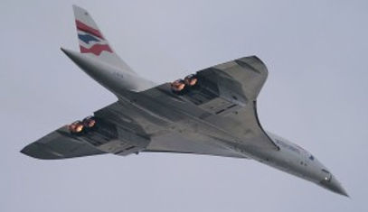
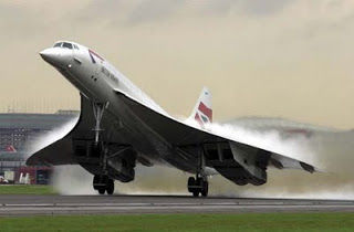
All swept wings create vortices (swirls of air) at their wing tips. The delta wing, however, as its angle of attack increases (at slower speeds), creates larger, slower moving vortices which creep forward along the leading edge, eventually enveloping the whole upper surface of the wing, thus further increasing the suction and therefore the lift.If you ever saw Concorde take off, or get a chance to see some pictures of her doing this on a really soggy day, you would see her half-disappear into a cloud of its own making, as the reduction in pressure forces water vapour supended in the air to condense.
Vortex lift is fundamental to Concorde’s ability to fly slowly. It also produced one of the characteristic qualities of the feel of Concorde to a passenger. The air swirling over the wing at slow speeds produced a bouncing motion, at a frequency of about half a second, which was sometimes mistaken for light turbulence. The motion soon disappeared once the speed had increased after take-off, but was there during final approach.


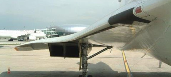
This picture shows the influence of the engines on the vortical flow field around Concorde, the engine nacelles; each one accommodates two engines are seen on the left-hand side along with the thrust


Air-flow around Concorde simulated landing
Lift generation on a delta wing
With aircraft that have straight and unswept wings, the flow separation results in a poor ratio of life to drag, and vibration due to instability of flow. However in aircraft with swept wings, such as the Concorde delta wing design. The separated flow will roll up into a pair of stable cone-shaped vortices. Unlike the bound vortex of a conventional wing, which merely represents the circulatory tendency, these are real vortices of swirling mass of air like in whirlwind.

The separated vortex flow represents an alternative method of lift generation. The airspeed in the vortex is high, and so the pressure is low. Thus, lift is still produced by exposing the upper surface to a low pressure than the lower surface; this low pressure is produced due to the vortex motion above it.At low angle of attack the generation of lift is the same as in the convention wing the effect of vortex lift comes into play only in high angles of attack.
The Slender delta-winged Concorde was designed to fly with separated conical vortex flow in normal flight conditions. The leading edge is sharp in order to favour flow separation even at small or moderate angles of attack
The strong conical vortex forms over the leading edge of the slender delta wing Concorde can be seen by vapour condensation
This conical flow may be thought as a controlled separation. When lift is generated this way, the wing will not stall in the conventional sense, and the lift will continue to increase for angles of attack up to 40 degrees or so. At the higher angles, the vortices start to break down, and the lift falls off. This method of lift generation is used in supersonic flights and it also has other advantage of postponing the sonic drag rise.Over 5000 hours of wing tunnel testing took place to modify its camber, droop and the twist, this was to ensure that the vortex that would be formed along the wing would be stable at the high angles of attack.


The strength and weight of the wing were very important in the design and construction. Instead of bolting and riveting sections together, the engineers used a process known as sculpture milling that starts off with a solid piece of metal. After that they used a numerically controlled milling machine to carve out the required shapes needed. The material used for this was copper based aluminium alloy, known as RR58 in the UK and AU2GN in France.
Concorde’s wing makes sense, there are many features that are different from that of other airliners. They all stem from the extraordinary range of speeds at which it had to be able to fly, from its ability to take off from Heathrow in the morning, cross the Atlantic at Mach 2, gracefully slow down to join the traffic flow into Kennedy Airport and land in sequence with all the other aircraft
Concorde wing design

Farnborough Air Sciences Trust delta wing development models
The wing was designed and then built in France, and can be broken down into nine distinct sections plus a number of smaller parts, that is on paper. In reality five major sections were fixed for life during the construction of Concorde. The big five sections are lateral slices comprising wing/fuselage/wing and together they form the structural heart of Concorde.The big five sections are lateral slices comprising wing/fuselage/wing and together they form the structural heart of Concorde.In general, the wing is a multi-spar torsion box built up from many comparatively small spar, rib and skin sections bolted together. Most of the spar and rib sections have been machined from billets or forgings, the skin panels from prestretched planks. The panels have integral stiffening webs.In the forward wing and in the wing section of the centre there are single-web spars where the spars are also fuel tank walls and pin jointed, tubular, lattice ribs set spanwise between the spars. There are no cordwise ribs in the forward wing area, which is attached to three fuselage frames by adjustable fittings

The big five sections are lateral slices comprising wing/fuselage/wing and together they form the structural heart of Concorde.
To the front spar of the centre section by a double row of countersunk bolts. It incorporates the forward trim tank No. 1
(See diagram below)


The wing sections of the rest of the centre section each have a few very strong machined spars which extend right across the airframe, as far as the leading edges and outer wings, and numerous cordwise ribs. Inboard of the engine nacelles these ribs are pin jointed tubular lattice frames. Above and forward of the engine nacelles the ribs, in addition to the spars, are machined components.
Examples of ribs. (Rips are numbered from 1 to 27 from the wing tip to the root. No. 17 is on the centre line of the engine nacelles)


The outer wings are torsion boxes of machined spars, ribs and panels. Each is attached to the centre sections by 340 high tensile steel bolts of various diameters. They embody the No.7 main fuel tanks and carry four of the six elevons. The outer hinges of the elevons are designed to permit spanwise expansion. The elevons themselves are honeycomb construction and are connected to each other by flexible joints.The leading edges are in 4ft sections which are structurally independent to alleviate thermal stress. The chemically milled skins are attached to machined ribs and extruded stringers and all sections are removable.The numerous inspections hatches in the surface of the wing are either quick-lock or screw fixed and none of them are load bearing.

As already mentioned above, the wing is of a delta type, and has orthogonal members in which the sealed structure forms the fuel tanks. The forward wing, intermediate wing, and outer wing form the primary structure of the wing. The leading edges form the secondary structure of Concorde’s wing, and the forward wing provides the continuity of the wing with the fuselage forward of frame 41.Several sections make up the intermediate wing which picks up with the upper fuselage. The intermediate wing rear section is so designed as to mount the engines as well as the elevens. Each section has machined AU2GN alloy skin panels in which access panels are provided to allow access to the fuel tanks, accessories and aircraft systems.There is a detachable outer wing which is attached to the intermediate wing and is equipped with the elevon attachments. The leading edges are also detachable and some are equipped with electrical de-icing.