Explore the world of Concorde with Heritage Concorde
Concorde Hydraulic Power supply
Originally there were four Hydraulic systems in the Concorde design, but the RED system was deleted, as it was felt to be superfluous. Airbus copied the hydraulic naming system (Green, Blue and Yellow hydraulic systems) for their aircraft from Concorde, although it was pinched for Concorde from the first jet airliner in the world, the British built Comet.
Concorde also used a special hydraulic fluid, Chevron M2V. This is a mineral based fluid, as opposed to the ester based Skydrol, used by the subsonic airliners. The reason that they went for a different fluid such as M2V was a simple one; Skydrol is rubbish at the high temperatures that Concorde operated at, no good at all in fact, so they needed something better and in M2V they found the perfect fluid. Aside from that unlike Skydrol, that attacks paintwork, certain rubber seals, skin, engineer’s eyes etc., M2V is completely harmless you could even wash your hair in it.

GENERAL DESCRIPTION
Hydraulic power is used to operate those aircraft services requiring a power supply which is substantial and instantaneous, and at the same time meets adequate safety requirements with a minimum of weight.
Safety considerations have led to the installation of independent systems together with one or more back-up systems to ensure operation of all vital services. The same considerations have also determined the number of pumps per system.
Main Power
Main power is supplied by two hydraulic systems:
- The Green system
- The Blue system
These two systems supply the power necessary for all the aircraft hydraulic services.
Auxiliary Power
Auxiliary hydraulic power is provided by several systems:
- The Yellow system
- The ground pressurizing system
- The ultimate emergency ram air turbine system
Yellow System
The Yellow system is used to replace a defective Green or Blue system.
Ground Pressurizing System
This system is used, on the ground only, for maintenance and testing operations.
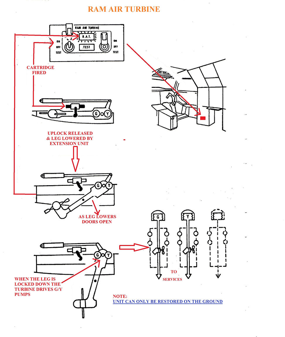
Ultimate Emergency System – Ram Air Turbine
The ultimate emergency system (ram air turbine) is used in the case of failure of the four engines. The ram air turbine is an ejectable aerodynamic spinner, normally retracted, consisting of a propeller driving two hydraulic pumps. The pumps provide the necessary hydraulic power for controlling the aircraft until it lands.
Fluid
The hydraulic fluid used is Chevron M2V. The hydraulic fluid is cleaned through filters in the hydraulic fluid. Hydraulic fluid temperature is kept stable by means of hydraulic fluid/fuel heat exchangers.
Pressure
Each system is pressurized to 4000 psi (275 bars) by two self-regulating -pumps driven by the engine accessory gear boxes. The pumps are mounted on the aircraft in such a way that in the event of a failure of the two engines, two hydraulic pressure systems remain available.
Hydraulic Tank Pressurization
In order to ensure that the pumps receive a satisfactory supply of hydraulic fluid, a tank pressurization system has been installed. The tanks are normally pressurized by air bled from the engines, and on the ground they can be pressurized by an air compressor.
Hydraulic Lines
The rigid HP hydraulic lines are mainly of titanium alloy with some steel. The LP lines are of aluminium alloy except in fire zones and special installations where steel pipes are used. On all titanium and steel pipes, brazed end fittings and removable couplings are used. On the light alloy pipes, standard AN fittings are used. Thermal expansion couplings, of the “Flight Refueling” type, are also installed to absorb any structural deformation (by bending or expansion).
Ground Connections and Sampling Valves
The hydraulic systems are provided with ground connections and sampling valves, which enable ground maintenance and testing of the systems.

The Hydraulics constitutes the lifeblood and muscle of Concorde. Without the Chevron M2V coursing through the network of pumps, pipes and valves, the lights would be on, but nothing would stir
There are three separate independent hydraulic systems. There are two main systems identified as Green and Blue and a standby system called yellow, which is available at any time for back-up purposes. Each of these systems is powered by two engine driven-pumps.

Green Hydraulic System
This system supplies power for normal operation of the following services:-
Landing gear including the doors
Nose wheel steering
Engines 1 and 2 air in-take ramps and spill doors
Nose and Visor
Main landing gear brakes with anti-skid
Tail skid actuator
Four motors for the engine air-intake ramps and the dump doors
One motor for the fuel trim tank 11 transfer pumps
On ram of each power flight control
One ram of each relay jack
Artificial feel
(The Green system also supplies the Emergency Generator hydraulic motor)
Blue Hydraulic System
This system supplies power for normal operation of the following services:-
Engine 3 and 4 air in-take ramps and spill doors
One Artificial feel jack on each flight axis
One tank 11 fuel pump
The second cylinder of each flying control actuator and of each flying control booster jack
Yellow hydraulic system
This system supplies power for standby operation of the following services:-
Engine 1m2, 3, and 4 air in-take ramps and spill doors
Flight controls
Nose and visor lowering
Landing gear lowering
Main landing gear brakes with anti-skid
Emergency and parking brakes without anti-skid
Nose landing gear wheel steering.
Normal and standby generation is provided by six engine-driven pumps that are mounted on the airframe accessory gearboxes on the engines: The two Green system pumps are driven by engines 1 and 2, the Blue system pumps by engines 3 and 4. The two yellow system pumps are driven by engines 2 and 4. These pumps pressurize the hydraulic system to 4000 psi (pounds per square inch), and in case of overpressure a pressure limiter allows a maximum pressure of 4500 psi. To prevent cavitation of the engine-driven hydraulic pumps, the three reservoirs must be pressurized. An auxiliary air compressor is provided to ensure that the three reservoirs are pressurized before engine start.

The systems are designed to work at temperatures between -40C and + 120C and the fluid used could withstand temperatures between -606 and +220C. To keep weight down and to obtain the required response rate at the controls the operating pressure was designed to be very high, hence the 4000 psi (pounds per square inch). During the flight between take off and landing, the yellow pumps are depressurized automatically (by means of a micro-switch operated by the landing gear) but they can be switched on from the flight deck.
These pumps are connected in such a way that each system has two pumps driven by a different engines and it will always be possible to use two systems if any two engines fail (see diagram1). Even after total engine failure the aircraft could be controlled in a glide descent by using the RAT (See below for further details concerning the R.A.T.)

All three systems are similar in design. From the reservoir, a line to each pump passes through a fuel-cooled heat exchanger and isolate valve. Pumps themselves have a solenoid operated off-load control and a cooling case drain flow routed through a case drain filter back to return. It is vital to keep a close check on these filters; any restriction in flow can lead to raised case pressure and pump-case separation, with the consequent system loss. Downstream, each pump output passes through an HP filter and non-return-valve before communing-up with its partner to supply aircraft services. All return flows combine to pass through an LP filter before returning to the reservoir.
Fluid must be supplied to pumps at a positive pressure. The Concorde method is to fashion the fluid contained as a stainless steel bellows, then surround with an airtight container, pressurized to 60psi using engine bleed air. A small electrically driven compressor is available to top-up the air pressure during ground servicing activities.
The reservoirs and charging points are located in the lower fuselage hydraulic equipment bay between frames 72 and 74 – frame 72 is the elevon attachment point. A special hand-pump charging gun is required; there is no gravity fill facility, thus no opportunity to top-up in flight
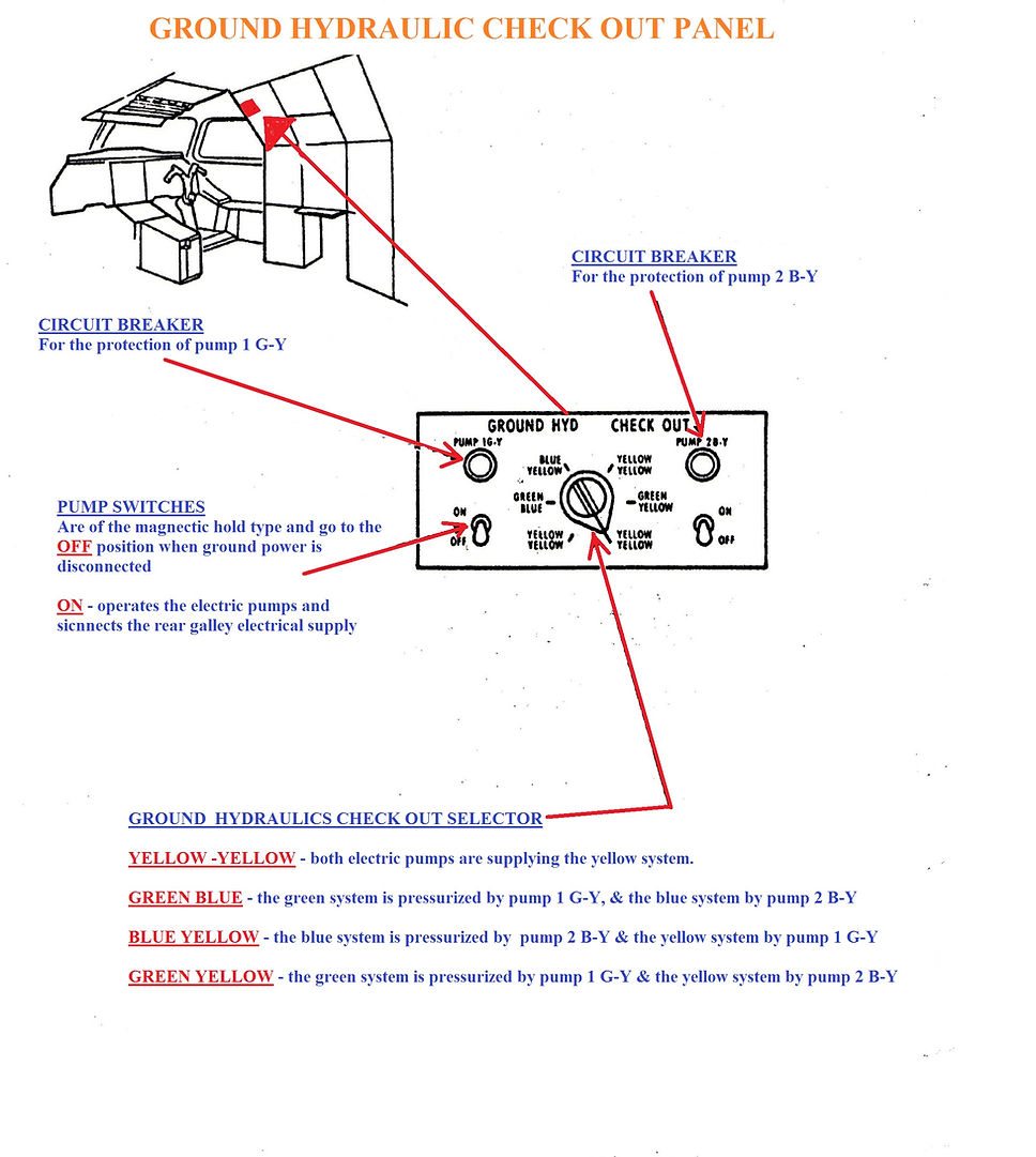
GROUND GENERATION
Ground generation is provided by two electrical Ground Hydraulic Check Out pumps that can be selected to pressurize the main and standby systems while the aircraft is on the ground. The maximum delivery pressure and flow of the electrical pumps is less than that of the engine-driven pumps.

EMERGENCY POWER
Emergency power is provided by a ram air turbine (RAT). This is a two-bladed propeller which provides power to drive two of the hydraulic pumps in the event of the engine wind-milling speed being insufficient to provide hydraulic and electrical power at subsonic speeds following a four-engine flame out.

AUTOMATIC PROTECTION FOLLOWING SYSTEM FAILURE
In the event of low pressure or tank low level in Green or Blue systems, a detection system automatically on-loads the Yellow system engine driven pumps and changes the hydraulic power supply for the appropriate ramp and spill door-actuators from Blue or Green system to Yellow.
In the event of a low level in the Yellow system reservoir, the first low level detection automatically inhibits the Yellow supply to:
(A) Nose wheel steering
(B) Flying controls
(C) In the case of a Yellow/Green selection the Yellow supply to main wheel brakes with anti-skid is cut off.
At a second low level, the Yellow supply to the in-take spill doors is cut off but this is overridden during manual inching on Yellow.
If a first low level cut off of the selected Yellow supply to flying controls occurs and a low pressure exists in the other side of the flying controls, there is an automatic change to Yellow supply to power the second failed flying control system.
If a GREEN ONLY or BLUE ONLY selection by the PFCU servo selector has been made and low pressure occurs in the selected system there is an automatic change to power the selected system with Yellow system.
If the flying controls are being powered by a single main hydraulic system after Yellow tanks low pressure cut-off and transfer of fluid from the operating system to Yellow tank causes both a low pressure in the operating system and Yellow tanks contents to rise above the low level cut-off, it is a design feature that Yellow system pressure will be supplied to both sides of the PFCUs.
THE FLIGHT ENGINEER’S HYDRAULIC MANAGEMENT PANEL


