Explore the world of Concorde with Heritage Concorde
Concorde RAT (Ram air turbine)
In aviation there is a saying, "when all else fails get your RAT out"
This is certainly not the case with Concorde although Concorde did have a RAT.
The Ram Air Turbine was used in the event of total failure and provided power for the flying controls and basic instruments.
Earlier Prototype and Pre Production aircraft had a monofuel based Monofuel Emergency Power Unit, this was considered far to dangerous for use at Airports so starting with F-WTSA RAT's were installed.

The ram air turbine (RAT) is used in ultimate emergency to provide the necessary hydraulic power for control of the aircraft in the event of failure of the four engines.
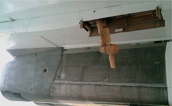
The RAT is normally stowed in the left inner eleven servocontrol fairing. It is ejected by a spring-powered ejection jack after being unlocked by a cartridge fired by means of a control on the 3CM’S panel.
Hydraulic pressure is generated by two pumps driven by a relative wind operated, twin blade, variable pitch propellor.
One of the pumps, supplied by the Green reservoir, pressurizes the Green system. The other is supplied by the Yellow reservoir and pressurizes the Yellow system.
The RAT can onLy be stowed manually on the ground.
Description
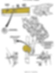
The ultimate emergency power system comprises :
A. A mounting bracket attached to the aircraft structure, upon which is fitted :
(1) The ram air turbine, consisting of :
- A propellor,
- A pivoted support Leg assembly.
(2) A gearbox.
(3) Two hydraulic pumps.
(4) Two hydraulic fluid distribution modules.
(5) The stowed position locking device.
B. An ejection jack.
C. Two HP filters.
D. A control panel.
The ultimate emergency system Green and Yellow pumps are connected to the normal Green and Yellow system suction and delivery lines via the Green and Yellow distribution valve modules.
These modules enable :
A. In both the Green and Yellow systems :
(1) Rapid attainment of speed by the propellor, by keeping a by-pass open between the suction and delivery lines of the pumps until their output reaches 60% of the rated flow.
(2) Filtering of the pump case drain fluid.
B. In the Green System Only :
(1) Filtering of return fluid from the propellor blade pitch control mechanism.
(2) Pressurization of the propellor blade pitch-control system by the Green pump in the event of very low temperature in the RAT housing.
Ram Air Turbine
General
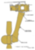
The RAT, in ultimate emergency, drives two hydraulic pumps which pressurize the Green and Yellow systems.
It consists of a variable pitch propellor mounted on the end of a pivoted support leg. The pumps are driven by the propellor via a mechanical transmission.
Turbine Assembly
(1) Description
The turbine assembly consists of a hub on which are mounted two blades, pitch variation of which is controlled hydraulically.
A latch engages in a notch in the hub, and locks the turbine assembly in the stowed position. The latch, controlled by a cam on the pivot shaft of the support Leg, frees the turbine when it is about 10° from its deployed position.
The pitch control system is installed in the hub casing. It enables the turbine to be maintained at a constant speed of rotation, whatever the relative
wind speed, or the hydraulic pump load.
It comprises :
- A pitch change control piston. The blades are rotated about their longitudinal axis by the forward movement of the piston, engaging an eccentric
pin.
In the absence of hydraulic pressure the piston is moved back into the rear position by a return spring.
- A pilot valve which controls the hydraulic pressure applied to the piston.
Valve displacement is controlled by governor weights and a return spring.
- An hydraulic gerotor pump, driven by the turbine and supplied from a Green hydraulic fluid circulation loop incorporated in the support leg.
An offload valve limits its delivery pressure rate.
Operation
(a) Rest position (Fig 3)
- System hydraulic pressure is at zero.
- The fly weights are in the rest position. The pilot valve, under return spring influence, is in the forward position, leaving the port clear for the passage of hydraulic fluid to the piston.
- The piston, under its own return spring load is in the rear position holding the turbine blades at course pitch.
(b) Speed adjustment (Ref. Fig.004 and 005)
The turbine begins to rotate at course pitch’ driving the pitch control hydraulic pump.
- The piston is moved forward by pressure from the pump and bears on the pin. The blades move towards fine pitch and their rotational speed
increases.
- The governor fly weights move away from each other and actuate the pilot valve, which gradually closes the fluid passage to the
piston.
- When the nominal turbine speed of 5200 r.p.m. is reached the pilot valve shuts off the passage completely. The piston remains steady,
in equilibrium between the hydraulic pressure and it’s own return spring.


(C) Speed reduction (Fig 006)
- When the turbine is operating at constant speed an increase in relative wind velocity or a decrease in the hydraulic power requirement entails overspeed.
- The fly weights move further away from each other, displacing the pilot valve which in turn causes the pressurized fluid acting on the piston to return to the gerotor pump inlet.
The piston is moved rearwards by its return spring. Thus increasing the turbine blade pitch, and decreasing turbine speed.
(d) Overspeed protection (Fig. 007 )
In the event of failure of the control system, two safety valves in the piston open by centrifugal force, when the nominal speed of rotation is exceeded by 20%. They release pressure from the piston, which is pushed back by its return spring. The propellor blades then adopt a coarser pitch, and the propellor speed decreases. The valves then close, thus functioning as an emergency control.
D. Support Leg (Ref. Fig.008 and 009)
(1) Description and Operation
The support leg consists of two concentric tube assemblies, which rotate relative to each other about the same axis.
The inner tube is hinged at the top on a mounting bracket attached to the aircraft structure. The pivot axis is the same as that of the gear box drive shaft.
The outer tube carries the turbine hub. A bevel gear segment at its top end mates with a stationary segment along the pivot axis of the inner tube.


In the course of RAT stowage or deployment the two segments provoke a 90° rotation of the outer tube about its longitudinal axis. This rotary movement allows the RAT to be housed in the small space available for it when stowed, and to position correctly in the airstream when deployed.
The support leg contains :
- The shaft transmitting turbine drive to the gear box, through bevel gears.
- Pipes forming the Green hydraulic fluid loop supplying the blade pitch change system.
- The locking system, which locks the turbine in a given position when the RAT is stowed.
The support leg also includes :
- A cam which operates the unlocking rollers of the fairing doors when ejection commences.
- A stowed position uplock roller.
- A downlocking system for the RAT when ejected.

5. Gearbox
The gearbox is attached to the mounting bracket at the leg pivot point.
It supports the two hydraulic pumps, to which it transmits turbine torque through a system of gears.
6. Pumps
7. Valve Modules
A. General
A Green and Yellow system distributor module are attached to the mounting bracket.
They contain the necessary components for distributing and filtering the hydraulic fluid for each system.
B. Description (Ref. Fig.010 and 011)
Each module consists of a forged aluminium alloy casing, housing various components.


c. Operation (Ref. Fig. 012 )
(1) Green Module
During RAT deployment, off-load valve (2) is open, forming a loop between the Green pump inlet (9) and delivery (8) lines. The turbine torque loading taken up by the pump is kept low, enabling the RAT to reach constant speed quickly.
When flow reaches about 60% of nominal. output the off-load valve closes rapidy, allowing the Green system, by means of a non-return valve, to attain normal pressure.
- A Green fluid circulation loop in the RAT support leg is supplied through a non-return valve. Green pump case drain fluid is fed into this loop, from
which it is returned to the Green pump inlet via the fiter.
- In the case of filter clogging, a by-pass valve opens and restores the return flow. A clogging indicator reveals the condition of the filter during
ground inspection.
- In the event of extremely cold conditions in the RAT compartment, which could affect the operation of the pitch change generator pump the control system is supplied by Green system pressure via a thermal valve. A non-return valve prevents the passage of the HP flow to the reservoir and pump inlet.
(2) Yellow Module
This also comprises :
- An off-load valve, to enable the propellor to reach constant speed quickly.
- A non-return valve on the Yellow pump delivery line.
- A filter on the line returning case drain fluid to the pump inlet, also a by-pass valve and clogging indicator.
The Yellow system is not used for operation of the pitch control mechanism.

8. Stowed Position Uplocking System
A. General
The RAT is retained in the stowed position by a lock. It is unlocking by a pyrotechnical unlocking device.
A manual unlocking device is provided for ground maintenance operations.
B. Description (Ref. Fig. 013 )
The uplocking system comprises :
(1) A roller, attached to the RAT support leg
(2) An uplock box, attached to the RAT mounting-bracket, consisting of a light alloy casing containing :
(a) Two independent push-rods each of which is operated when the associated cartridge is fired.
(b) A main crank lever.
(c) An intermediate crank lever, with return spring and roller.
(d) A pivoted catch, with return spring and notch.
(e) A manual unlocking cam.
c. Operation
(1) Uplocked position.
The support leg roller engages in the catch. The intermediary crank lever, held in position by a return spring, locks the catch by means of the roller
engaging the notch.
(2) Uplock Release In Flight
Firing of one of the uplock release cartridges operates a push-rod, which tilts the main crank Lever. The main crank lever then actuates the intermediary crank and disengages its roller from the notch in the catch.
The catch, under spring pressure, opens and frees the RAT support leg roller.
(3) Uplock Release on the Ground
The intermediary crank lever is actuated in the same way as the main crank lever, by means of a cam turned by a wrench.
It regains its initial position under return spring pressure.
9. Ejection Jack
The ejection jack provides the force necessary for deploying the RAT, and opening the fairing doors.
The cylinder rod of the jack, under spring pressure, operates a lever attached to the propellor support leg.
An incorporated hydraulic damper checks and controls the cylinder rod movement.
10. Control Panel
A. General
The uplock release cartridge firing electrical system is controlled from the 3CM’S panel..
B. Description and Operation (Ref. Fig. 014 )
The control panel. includes :
- Two 3-position selector switches :
- OFF- stable rest position
- ON- controls RAT ejection. To obtain this fixed position it is necessary to remove a sealed cover guard.
- TEST- for monitoring electrical circuit continuity.
This is an automatic reset position, the selector returning to OFF when released.
- A green RAT indicator Light, which illuminates when the fairing doors are opened for ejection of the RAT.
A blue TEST Light, which illuminates when one of the selector switches is in the TEST position, and the corresponding cartridge firing circuit is closed.


Other images